Project Overview
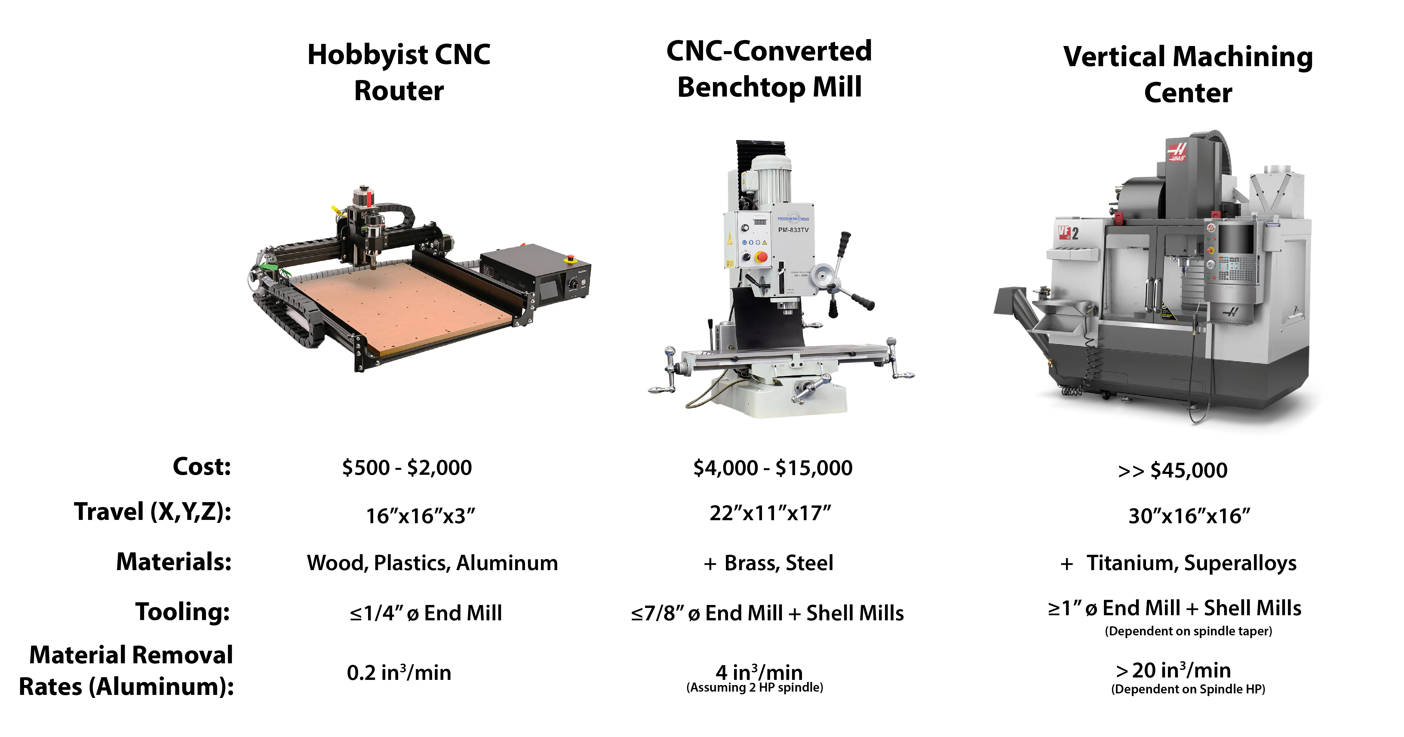
The ability to machine metal is perhaps the ultimate goal of the DIYer. And while a low-cost CNC router may allow you to take small bites out of aluminum, it’s clear that a more powerful and rigid machine is necessary to efficiently shape metals. However, most garage shops do not have the space, power requirements, or even budget for an industrial sized milling machine, such as a Fadal or Haas. Fortunately, there is a middle ground between the full-fledged vertical machining center (VMC) and a CNC router: A Bench Type (or Benchtop) Mill.
While somewhat of a misnomer, benchtop mills do require a bench to be at a proper height for operating, but with models ranging from 300 to 1500 pounds a heavy-duty stand is usually preferred over a standard workbench. However, even with their own stand, the footprints of benchtop mills are small, allowing for most to be moved in and out of residential doorways and placed in a crowded garage. For heavier benchtop mills, special rigging equipment, such as a forklift or engine hoist, is often required to get the mill to its final location.
To Convert or To Buy
Benchtop mills can be purchased as manual instruments, which can be converted to CNC, or can be bought as ready-to-run CNC machines. Tormach is the most well known supplier of CNC benchtop mills, with the 770M and 1100M being the most affordable. However, these machines still cost $9,000 and $11,500, respectively, without a stand or any useful features. If you purchase a similar size manual machine from Precision Matthews or Grizzly, and convert it to a CNC machine yourself, then you have the opportunity to save up to 50% on these sticker prices.
Of course, these cost savings do not account for the time it takes to convert the mill, the inevitable broken parts, and the absence of a warranty. These reasons will deter many from going down the conversion path, but for those who do, the real value of DIYing a CNC mill is an intricate understanding of how the mill works, allowing you to diagnose and fix problems without expensive technical help and OEM parts.
Before embarking on your conversion, it is important to note that you will have to be creative in your approach. Haphazardly drilled mounting holes are standard on all imported mills, which often requires motor and ball screw brackets to be modified. Hard to reach fasteners may require comically long socket extensions. Just be careful to not put yourself in a compromising position where the mill could fall on you.
Which Manual Benchtop Mill?
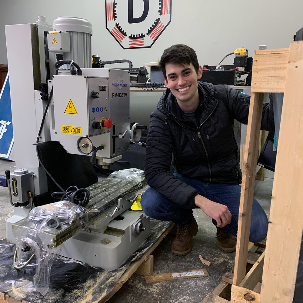
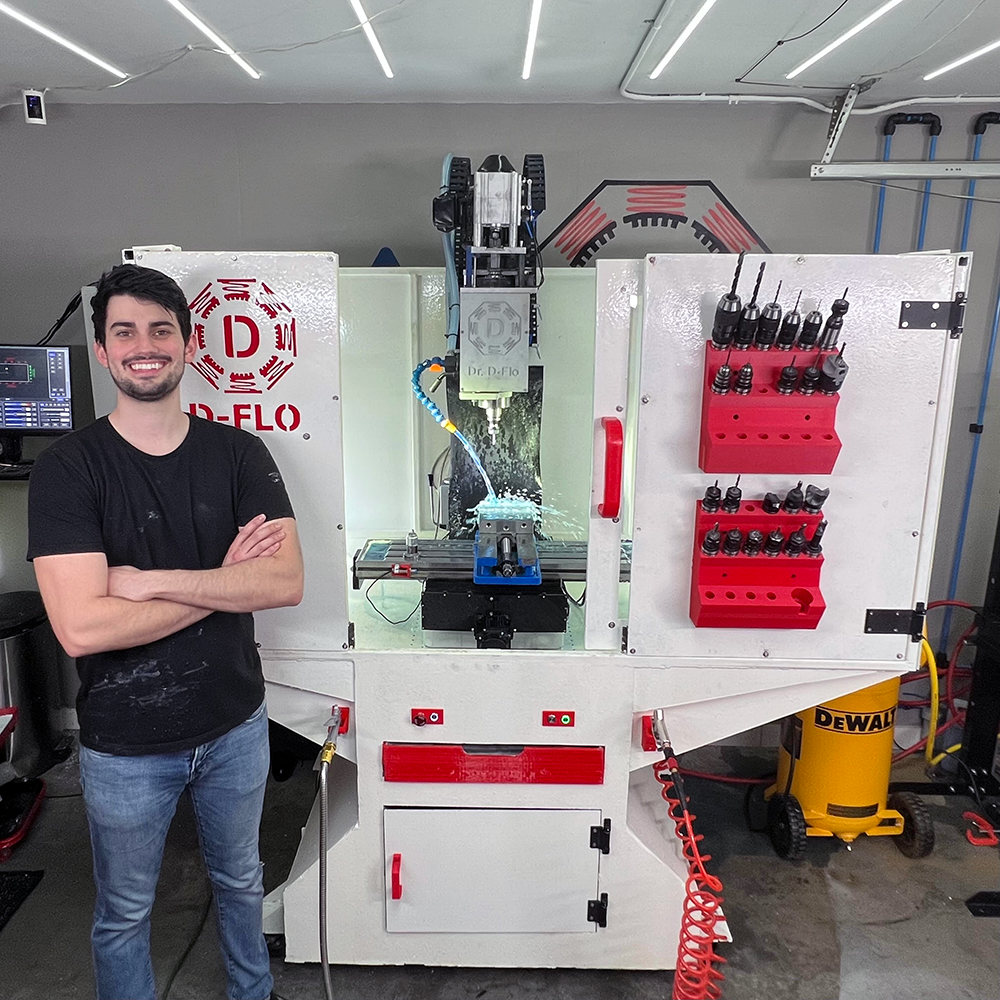
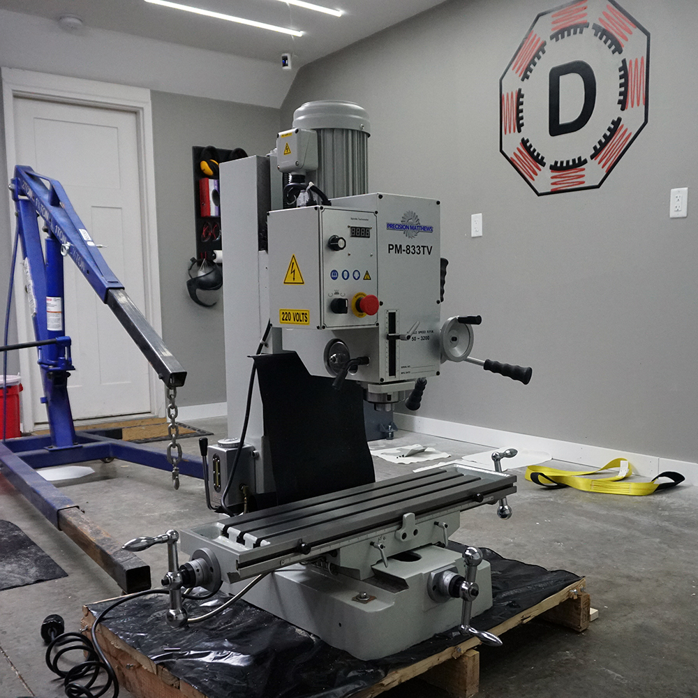
Dr. D-Flo with his freshly uncrated PM-833TV
You may be surprised to find many different benchtop models that seemingly look the same but have widely different price points. This is because most benchtop mills take after the Rong Fu 45 (RF-45) form factor, where dovetails ways allow the table to move in the X and Y and the head to move up and down a square column. Further, all RF-45 variants use a R8 spindle and are compatible with the same affordable tooling as a Bridgeport-style mill. The cost differential is a result of mills with larger travels, heavier castings, and more powerful spindle motors.
Please note: Benchtop mills with a round column, such as the Grizzly G0760, are not suitable for CNC conversions as there is too much slop when moving the spindle head up and down. A square column with dovetail ways is a must.
In the United States, my favorite retailer for benchtop mills is Precision Matthews because of their prompt customer service, but most other companies receive their machines from the same factory in either Taiwan or China. Once you decide on a reseller, I recommend selecting a mill based on the following criteria:
- Prioritize travels. The total movement in each axis is a non-upgradable feature but will directly affect the size of parts that can be created. Of course, a mill with larger travels will be a larger, heavier machine. Therefore, select a mill that has the capacity for your parts but still fits in your space.
- Maximize weight. With all other specifications being equal, a heavier casting will be more rigid, increasing the material removal rate. Be sure that you have the correct equipment, such as an engine hoist, for moving the mill components during the conversion.
- Go direct drive. Benchtop mills are sold with geared (indirect) or belt (direct) spindle drive systems. Direct belt-driven spindles are easier to upgrade (e.g., rigid tapping), quieter, and allow for higher spindle speeds for making quick work of aluminum.
- Opt for a one-shot oiler. Dovetail ways restrict the motion of each axis through sliding metal features that need to be well lubricated to prevent permanent damage. A mill with a one-shot oiler or even better an automatic oiler will already have the lines and ports installed for easy lubrication.
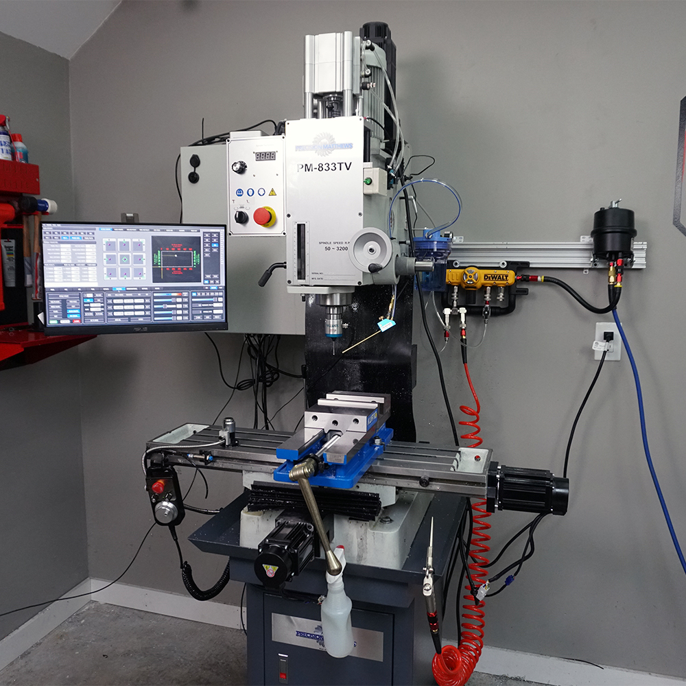
Given these criteria, I selected the PM-833TV as the mill that I would perform my CNC conversion on. It is one of the larger benchtop mills with a X-axis travel of 22”, Y-axis travel of 11”, and Z-axis travel of 17”. It also weighs in at 750 lbs, which is heavy but still manageable for someone who only has access to an engine hoist. The spindle is directly driven by a 2 Hp motor, which is about as powerful of a motor as one can get on this form factor. And finally, this mill has a one-shot oiler installed, which will improve its longevity and performance.
You may select a different benchtop mill, such as the G0704, PM-25, or similar, based on your requirements and budget. But with the similarities between these RF-45 style mills the upgrades and features discussed on this project page can be adapted to any benchtop mill.
CNC Conversion
When converting a mill, money and time are inversely related. This principle holds true for most projects. If you want to spend less money, then you are going to have to put more time into the conversion by building some of your own parts or by figuring out how to use free, open-source software. If you are not electrically inclined, then it might make sense to purchase a more expensive but user-friendly control system, like the Centroid acorn. If you do not have access to a mill, then you will have to purchase the motor mounting brackets and plates from a conversion kit provider.
It’s important to have the correct mindset when converting a mill to CNC. Are you taking on this project because you want to quickly turn a profit by making parts in your garage? Or is your goal to learn about CNC motion and machining by building? In my opinion, the latter mindset will be more successful. If you are in a hurry, then it is my strong recommendation to purchase a turnkey system.
It may seem like an omission but the CAD files for the motor and lead screw nut mounts to convert the PM-833TV are not available on this website. I purchased my plates from Bruce Nelson at Heavy Metal CNC. Unfortunately, Bruce passed away and Heavy Metal CNC has ceased operations. Arizona CNC Kits is my recommended supplier for all Precision Matthew CNC conversions. The rest of this guide will focus on my novel upgrades (enclosure, flood coolant, inverter-duty motor, etc.) and will include all CAD files and bill of materials.
Resources
The BOM contains parts for two configurations: 1) An open-loop stepper motor configuration - cheaper and simpler. 2) A closed-loop AC servo motor configuration - smoother, faster, and positional feedback. Stepper or servo specific parts are denoted in the section headers.
Please note: Heavy Metal CNC is out of business. But Dave from Arizona CNC is selling a kit for the PM-833TV.
† AC Servo motors have a low rated torque compared to a similar size stepper motor. However, they possess a high instantaneous torque that can be used intermittently, which makes up for the difference.
The BOM may contain affiliate links that provide monetary kickbacks to Dr. D-Flo. These funds are used to pay for this website and future projects.
Quick links to topics covered in each video of the manual mill to CNC conversion series.
- A little self-promotion here, but if you are new to CNC motion, then checkout my written guide and video on how to build a 3D printer. Many of the concepts that go into building a 3D printer translate over to a mill conversion (just on a larger scale).
- The LinuxCNC Wiki and forum are invaluable resources if you use this open-source software to control your mill.
- The book CNC Milling in the Workshop is great for beginners
- If you are using the DMM servo motors, then definitely watch this setup guide for the DYN4 drives and motors.
Upgrades
Installing ball screws and motors is just the tip of the iceberg for converting a manual mill to CNC. There are so many upgrades that can improve the machine’s productivity, capabilities, and surface finish of parts.
Below is a list of all the upgrades my mill is currently equipped with. Each upgrade is hyperlinked to its own section in this guide and/or external links to a kit (e.g., power drawbar). These upgrades are in order of importance.
- Gas Springs - The Z-axis motor has to fight the friction of the dovetail ways and the weight of the spindle head. Further, the spindle head cannot drop if the mill loses power. Gas struts can remove some of the load allowing for lower motor torque and faster Z-axis speeds.
- Power Drawbar - A pneumatic cylinder presses on the drawbar to release a TTS tool holder. Most milling operations require multiple tools and a power drawbar allows for a quick change of cutters with repeatable z-offsets.
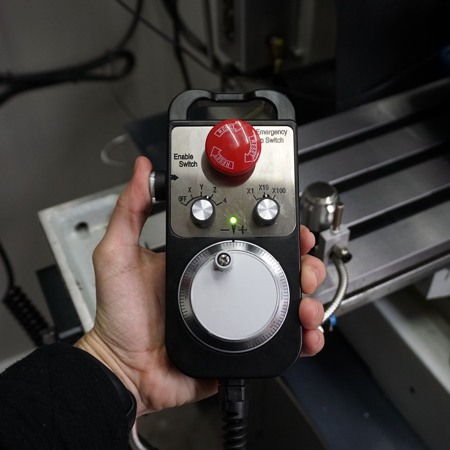
- Jog Pendant - A remote control for the mill! Precisely move the mill to prepare for a probing routine or check clearance.
- Mist Coolant (MQL) - Clear chips and lubricate the cutting surface to increase the life of your cutters and improve part surface finish. Only a small amount of coolant is used, so no enclosure is necessary.
- AC Servo Motors - Upgrade your stepper motors to AC servo motors for faster and more efficient performance. The positional feedback of a servo motor can also stop the mill if an obstacle is met (e.g., installing the wrong tool and swiping the vise or part during a rapid).
- Enclosure - Safely and cleanly run your milling machine when it is behind an enclosure.
- Inverter-Duty Motor - Upgrade to an Inverter-Duty motor for increased low-speed performance when cutting steel or performing rigid tapping.
- Spindle Encoder - Track the rotation of the spindle for precise RPMs or to synchronize the rotation of the spindle with the Z-axis for rigid tapping.
- Tool Setter - Touch off your cutting tools to automatically determine their length.
- Flood Coolant - For the best surface finish and longest tool life, blast all chips away with a flood coolant.
Gas Springs

The spindle head, which carries the motor, spindle, drawbar, and cutting tool, is quite heavy. The Z-axis has to overcome both the weight of the spindle head and the frictional forces between the dovetail ways. For this reason, the Z-axis motor is the largest (and most expensive) of the three required motors and often requires an electromagnetic break to prevent the spindle head from dropping when the mill is not powered on.
Even with an appropriately sized motor, the weight of the spindle head can result in slow accelerations and speeds. The Z-axis is constantly retracting and engaging the cutting tool as separate features are machined. A slow Z-axis results in slow cycle times.
Gas springs or gas struts are pistons that use gas (usually nitrogen) to provide a controlled force when compressed. Gas springs can be used to counterbalance the weight of the head, making it quicker for the motor to adjust the vertical position of the spindle or allowing for a smaller, cheaper motor to be used for the Z-axis.
Gas springs are sold based on their stroke length and compression force. The stroke length should be long enough to not inhibit the motion of the Z-axis. Selecting the compression force is less intuitive as you do not want it to completely offset the weight of the spindle head. Some downward force exerted by the spindle head eliminates backlash in the Z-axis.
Most gas springs will be rated by both their extension force and compression force. As two gas springs will be used in this upgrade the compression force multiplied by 2 should not be greater than the weight of the spindle head. During the conversion, it is recommended to weigh the spindle head with a scale. 20-30 lbs of downward force after counterbalancing with the gas springs is ideal.
Gas springs only work in one direction and should run parallel to the Z-axis. Due to the shape of most benchtop mills’ castings, the sides of the spindle head need to be increased to allow the springs to be perpendicular to the base. I framed the spindle head with four machined pieces of aluminum that used existing mounting holes of the accordion way covers. The CAD file is provided in the resource section but will likely need to be modified even if you have a PM-833TV. A gas spring with 40-60 lbs of compression force will likely be suitable for many benchtop mills.
Enclosure
From a safety and cleanliness perspective, an enclosure is an absolute must. Unfortunately, most benchtop mills come with a flimsy stand that does little to keep chips and coolant from flying all over your shop. In my latest YouTube video, I designed and welded together a steel enclosure that not only contains the mess that is subtractive manufacturing but also is compatible with flood coolant systems. Coolant and fine chips travel down the sloped basin into a chip drawer, where only the coolant is returned to a reservoir.
The provided Fusion 360 model is parametrized, which allows for the dimensions of the enclosure to be quickly updated to fit your mill.
If possible, please download the model by clicking “Open in Fusion” in the 3D model viewer above. If you encounter any issues with loading, or if you prefer using a different CAD program, you are welcome to download the .F3D or .STEP files provided here . Please be aware that due to the substantial size of these files, opting for this download method contributes to higher hosting costs for this website.
This enclosure designed is licensed under BY-NC-SA 4.0. Users are allowed to adapt and remix the work but all contributions must be distributed under the same license as the original (e.g., noncommerical). The 3D model or physical models produced from this digital design cannot be redistributed or sold.
If you would like to purchase an enclosure kit for the PM-833TV mill or for any other benchtop mill then please email Dr. D-Flo. Kits will include plasma cut sheet metal that must be welded together. All other components must be purchased separately.
Assembly of the enclosure is relatively self-explanatory after close inspection of the Fusion 360 CAD model and watching the enclosure YouTube video. This will be a quick guide on how to adjust the model to fit your mill and how to avoid some potential pitfalls.
Modifying CAD Model
Adjusting Important Parameters
Open the enclosure design in Fusion 360 by clicking on the interactive model above. Once loaded, in the design workspace go to modify then change parameters. A table will appear with important variables that control the overall size and fit up of the enclosure. I have summarized the most important parameters below.
Please note: This model was not tested for extreme changes of the parameters (e.g., doubling the size of the enclosure). For Dr. D-Flo’s help with modifying the enclosure or overall assembly, you must purchase a kit, but there are many Fusion 360 resources available online.
Parameters
- Base_Sheet_Metal_Thickness is the gauge of the sheet metal used to construct the structural components of the enclosure (i.e., the base). The default value is set for 0.25” (6.35 mm).
- Basin_Walls_Metal_Thickness is the gauge of sheet metal used to construct non-structural components, such as the bottom of the basin as well as the upper walls of the enclosure. The default value is set for 16 gauge material (1.6 mm).
- Female_Tab_Width and Female_Tab_Length are parameters that control the width and length of the slots used for joining sheet metal components together. Female_Tab_Width will be a function of the sheet metal thickness used to construct the enclosure and should be set large enough to accommodate any inaccuracies from the plasma cutting process. It is recommended to perform test cuts with the female slot and male tab dimensions before cutting out all components.
- Male_Tab_Length and Male_Tab_Width are parameters that control the length and width of the tab. The tab length should be set in conjunction with Female_Tab_Length. The tab width will determine how much the tabs stick out of the slot. Larger stick out makes assembly easier but requires more material to be grinded away for a smooth finish.
- Mill_Base_Slat_Spacing is the spacing between the rectangular tube stock that the mill will sit on. This distance should be set to distance between centers of the mounting holes of the benchtop mill. The default value of 317.5 mm is set for the PM-833 mill.
- Basin_Right_Length is the distance the top (i.e., basin) of the enclosure extends from the center line to the right. This should be carefully set to be sure that there is clearance for the full travel of the table.
- Basin_Left_Length is the distance the top (i.e., basin) of the enclosure extends from the center line to left. This should be carefully set to be sure that there is clearance for the full travel of the table.
- Base_Depth is how deep the enclosure is. If the thickness of the tube stock used to construct the top of the enclosure is subtracted from Base_Depth the resultant value multiplied by (Basin_Left_Length + Basin_Right_Length) would equal the total free area within the mill enclosure.
Be sure to play around with this model and understand how changing the parameters affects the inside and outside dimensions of the enclosure. If the enclosure is significantly enlarged, then the components may no longer fit on a 4’x8’ plasma table. Also, the drawer slides for the center door do not update when the dimensions are changed. You may have to purchase smaller or larger slides based on your modifications.
Exporting Enclosure Parts to Plasma Cutter
For those who use Fusion 360 to control their CNC plasma table, it is easy to go into the manufacturing workspace and create toolpaths to cut out each panel. For others who use 3rd party software, you must export each part as a DXF file. This can be accomplished by going to the browser on the right, expanding a component, going into the sketch folder associated with that component, and then right clicking on the sketch and saving as a DXF (process pictured below). The export tool can also be used (read more here).
Please note: Some sketches contain construction lines, which should not be cut. Closely inspect that each DXF file is accurate and complete.
Assembly
If you took the time to calibrate the dimensions for the tabs and slots, then this enclosure should go together as easy as a puzzle, albeit a very a heavy puzzle! The design does not rely on welds for structural support, but instead as more of a “glue” to make sure the pieces stay put. Avoid running long weld beads as this can cause the sheet metal to warp, making it difficult to fit later pieces. Instead use short spot welds spaced evenly across seams/joints. The enclosure YouTube video shows the correct order to assemble it. The bottom basin pieces must be installed before adding the “Top-Skeleton.”
The tools used to cut and weld the enclosure:
Enclosure Cost
The cost of the enclosure is heavily impacted by current sheet metal prices. Four 1/4"x4’x8’ ($350 ea.) and three 16 ga x4’x8’ (100 ea.) mild steel sheets are required. At current, post-pandemic prices the raw material costs are $1,700, which is almost double from two years pior. The hardware, consisting of four wheels ($60 ea.), two slides ($30 ea.), four small hinges ($20 ea), and two large hinges ($30 ea.) add another $440. The three 1/4” polycarbonate windows were another $300. Two gallons of paint (primer: $134, white epoxy paint: $94) added a final $228. This brings the total to almost $2,700. However, there are some hidden costs, such as consumables for the plasma cutter, drill bits, and flap disks for removing dross.
For reference, a Tormach stand and enclosure (my design doubles as both) costs close to $6,000. Of course, such a stand is not compatible for most imported benchtop mills, but it is important to put the price into perspective. So if you have a welder, plasma table or purchase the kit from myself, and free time, then there are cost savings to be had.
Enclosure Updates
If you are following along with this project, then you will benefit from my hindsight. The Fusion 360 model has been updated to improve issues with my first iteration. These changes include:
- Increasing the height of the cutout for the chip drawer.
- Moved and grouped the drainage holes in the basin sheet metal to be away from the rectangular tube stock. Surface tension would cause a small amount of coolant to track along the tube stock, missing the chip drawer and eventually ending up outside of the enclosure.
- You may prefer to bolt the enclosure panels to the inside of the upper frame. With the panels on the outside, you must use sealant at the bottom seam, so that coolant won’t leak out.
Flood Coolant
Flood coolant has been a game changer. The obvious benefits of increased chip evacuation and a cooler cutting surface are very much evident on machined parts. However, the benefit I've enjoyed most is that the flood coolant operates independently of compressed air, which is not the case with my minimum quantity lubrication (MQL) or mist coolant system. MQL notoriously consumes a lot of shop air, and my small compressor was always running to keep up. In a small garage shop, a compressor can be deafening, and I would have to wear ear protection when machining. Now operating the mill is less jarring as it sounds like an indoor water feature.
Flood Coolant Path
Starting at a reservoir located in the base of the mill enclosure, coolant is pumped up to the machine tool, which cools and removes chips from the cutting process, before being recaptured back into the reservoir. This relatively simple loop does require several careful considerations:
- Sourcing a pump with a sufficient flow rate.
- An immersion coolant pump with 1/8 hp is likely sufficient for most benchtop mill applications. However, a 1/4 hp pump will provide additional chip clearing capacity.
-
Removing chips and oil from the return coolant.
- Large and fine chips alike need to be removed from the coolant before heading back to the spindle. Failure to do so could clog the coolant nozzle or at the very least result in a deteriorated surface finish as the part is pelted with previously cut chips. To remove large chips, a mesh with 0.015” or 0.4 mm openings is installed in the chip drawer. Small chips (< 50 microns) are subsequently removed through an inline filter.
- Tramp oils are any unwanted hydro-carbon-based materials that contaminate the coolant. For benchtop mills, the largest source of tramp oil is the lubrication for the dovetail ways. When way oil gets into the coolant, it affects the cooling performance and promotes anerobic bacteria growth. An oil skimmer, such as this one, should be used to remove tramp oil from the reservoir.
-
Regulating coolant pressure and providing an alternative route for the coolant if the path to the machine tool is blocked.
- The coolant line can become blocked for several reasons, such as a kink in the line or a plugged-up filter. If the milling machine is running unattended, then the coolant pump could overheat if it is unable to move the coolant. A low-PSI pressure-relief valve allows the coolant to keep circulating even if the main loop is blocked. This component also allows for the coolant pressure at the spindle to be decreased if there is too much splashing.
-
Compatible fittings, tubing, and paint!
- Modern coolants (more information below) can degrade plastic components, including tubing and fittings, as well as the paint used to protect the enclosure. A good rule of thumb is to avoid amorphous polymers, such as ABS and polycarbonate, which are susceptible to chemical attack. The only exception to this rule is polyvinyl chloride (PVC), a preferred material for coolant tubing. However, it is best to opt for all metal components, where possible.
- Coolants have also been known to attack paints and coatings applied to the inside of the enclosure. Epoxy-based paints are preferred for their chemical resistance.
Selecting a Coolant Concentrate
There are four main types of coolant suitable for machining: neat oil, soluble oil, semi-synthetic, or full synthetics. We will cover each classification, but there are advantages and disadvantages of each type depending on requirements of cooling, lubrication, corrosion protection, sump life, and metal compatibility. Some coolants can contain toxic additives, so it is always best to handle with PPE and consult the safety data sheet prior to use.
Neat/Straight Oil: With the highest lubricity of any coolant type, straight oils will result in an excellent surface finish. Further, mineral oil affords great corrosion resistant. However, this coolant has poor heat dissipation properties and a low flash point, posing a serious fire risk. Straight oils should only be used for low-speed cutting operations and is not recommended for CNC operations, especially for garage shops without fire suppression.
Soluble or Emulsified Oil: Using emulsifiers, oil can be evenly dispersed in water to form a stable solution that has the lubricity of an oil-based coolant but also the high cooling capacity of a water-based one. Further, the high water content prevents autoignition of coolant mist, and hence, is less of a fire hazard. Unfortunately, this type of coolant has a low sump life due to bacteria growth that feeds off the emulsifiers.
Semi-Synthetics: Semi-synthetics is a coolant mixture of part oil, part polymer (i.e., synthetic), some additives, and the rest water. Both the emulsified oil and water soluble polymer work in tandem to lubricate and cool the cutting operation. The lower mineral oil content means less foaming (emulsifiers trap air), less bacterial growth, and better rejection of tramp oil, improving sump life.
Synthetic: Full-synthetic coolants do not contain oil but instead are composed of various polymers and chemical compounds to replicate oil’s natural lubricity. This is the cleanest coolant type as it readily rejects tramp oil and inhibits bacterial growth. However, the track record of corrosion protection is spotty but improving for synthetic coolants.
For my garage operation, I am currently using Fusion Cool 2240, a semisynthetic coolant that can be purchased by the gallon from Amazon. Due to the clear nature of this coolant, it is likely that the oil content is low (~5-10%), but I have yet to see any issues with rust. For a higher oil content and better lubricity consider Fusion Cool 2275.
When mixing coolant concentrate with water, always add the concentrate to the water to ensure the emulsion forms correctly. Also, be sure to check the coolant concentration often with a refractometer, too low of a concentration can result in rust and too high could lead to deposits on the mill.
An interesting solution: way oil that becomes coolant. CMTeamCobra, a commenter on the enclosure YouTube video, suggested combining Oemeta Hycut SW 68 way oil, which is water miscerable, with semisynthetic Oemeta Novamet 910 coolant. With this combination, the way oil becomes coolant instead of tramp oil when it reaches the reservoir, eliminating the need for an oil skimmer.
Inverter Duty Spindle Motor (Rigid Tapping Upgrade)
Geared vs. Direct Drive Spindles
Many benchtop mills, including the PM-833, are offered with two spindle drive systems: 1) Geared 2) Belt. Geared spindles offer a handful of discrete speeds typically from 60 to 1500 RPM. Even at low speeds, they have high torque, which makes this drive system best for machining steels. Belt drive spindles have 2-3x the max RPM of a geared setup and thus, are preferred when machining aluminum and other soft metals as more material can be removed quicker. Further, the speed of belt driven spindles can be adjusted by turning a knob on a variable frequency drive (VFD). However, to save costs, nearly all benchtop mills are shipped with general purpose motors, which overheat at low RPM and have a narrow constant torque speed range. The gear reduction in the geared spindles allow general-purpose motors to run at their optimal speed, but to change the speed of a spindle driven by a belt, the speed of the motor must to be decreased.
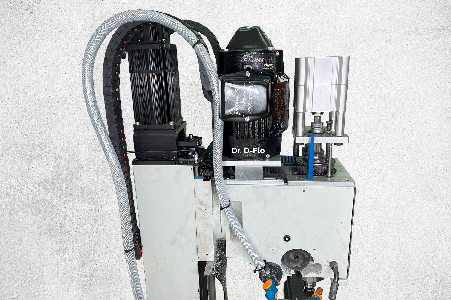
Inverter Duty Motors
To achieve low RPM operation without shortening the life of the motor and losing torque, an inverter-duty motor, such as the 2hp Marathon Y551, should be used. With this type of motor, a belt-driven spindle is suitable for cutting steels and most importantly for rigid tapping. Rigid tapping is the process of synchronizing the rotation of the spindle with the descent of the headstock to match the pitch of a thread tap. Milling machines capable of rigid tapping can quickly thread many holes without special compression holders. However, this process occurs at low spindle RPMs and requires high torque. Consequently, upgrading the stock general purpose motor is a must.
Inverter-duty motors are typically larger and heavier than general purpose motors as they rely on a cast iron frame and often cooling fins to dissipate heat. General purpose motors use a shaft-mounted fan for cooling, which is one reason why these motors perform poorly at low RPM because their cooling rate depends on the shaft’s speed. Therefore, an inverter-duty of similar power will take up more space than its general-purpose counterpart. I was barely able to squeeze the Y551 motor with its 145TC frame onto the mill headstock without running into the column. For smaller mills, a spacer between the headstock and Z-axis saddle may be required for clearance.
VFDs
Most AC induction motors suitable for driving a spindle, including the Marathon Y551, are 3-phase motors. Put simply, a 3-phase motor requires three AC waveforms that are 120 degrees out of phase with each other for power. Compared to a 1-phase motor, a 3-phase motor produces higher starting torque, more consistent power delivery, and is more efficient.
Unfortunately, most residential garages only have single phase power, but even if your benchtop mill was at an industrial facility with 3-phase power, then you would still be limited by a single output speed of the motor. This is because the speed of the motor is directly proportional to the frequency of the incoming AC power. In the United States this frequency is fixed at 60 Hz (most other countries use 50 Hz), which results in a rotations per minute (RPM) of 1800 (for a motor with 4-poles). This speed is too fast for rigid tapping, which occurs around 300-500 RPM, and is too slow for efficiently cutting aluminum.
A Variable Frequency Drive or VFD is a device that can vary the frequency of supplied AC power to the motor, allowing for speeds higher or lower than the rated speed of the motor (speed at 60 or 50 Hz). Most inverter- or vector-duty motors can safely operate from 0 to 180 Hz or 0 to 5400 RPM from the previous example. All VFDs can supply this frequency range, but some VFDs also offer additional features, such as converting 1-phase to 3-phase power and/or stepping up voltages.
The ability of a VFD to take 1-phase power and simulate 3-phase power allows hobbyists and small shops to run these induction motors off residential power. However, the supply voltage of the motor is one more hurdle that must be overcome. Most AC motors have a low and high operating voltage, which the end-user can switch between by changing the wiring coming out of the motor. The low voltage is typically 220V. While not an issue for most countries, residential plugs in the U.S. are 110V. It is possible to purchase a VFD, such as this one, that can step up 110V to 220V and convert it to 3-phase power, but this is not recommended as the lower voltage will result in a high current draw (12 to 15A for a 2 hp motor). The preferred approach is to install a 220V breaker and plug, as nearly all US houses are supplied with 220V power, which is split up into 110V. When opening your breaker box, you may notice double breakers with a label for a power hungry appliance, such as a washer or dryer. These appliances run off 220V and so should your spindle motor!
VFD Control Methods
Up to this point, the VFD’s control of the motor’s speed has only been discussed in terms of frequency. In reality, the VFD varies both voltage and frequency through a process known as Pulse Width Modulation (PWM). In classic V/Hz control, the VFD changes the output frequency (Hz) and voltage (V) linearly to change the speed. For example, if a motor is running at its rated speed of 1800 RPM at 60 Hz and 220V, then it would run at 900 RPM when supplied 30 Hz at 110V. While a lot can be said about V/Hz control, the most obvious limitation of this open-loop control method is that the VFD does not check how the motor responds to its commands. It assumes that the motor is changing speed appropriately in response to new frequencies and voltages. This assumption leaves a lot of accuracy and performance on the table.
Sensorless Vector Control (SVC) is a more sophisticated control process, where the VFD can measure how the motor is responding to speed changes and variable loads without an external sensor (hence, sensorless). SVC results in both improved low speed operation and torque control, which are both important for rigid tapping. Consequently, always select a drive with SVC for a spindle motor.
Check out this document by Rockwell Automation for more details on the different VFD control methods.
Purchasing a VFD
Given this information, a VFD should be sourced with the follow specifications:
- Input Voltage: 220-230V
- Input Phases: 1
- Output Voltage: 220-230V
- Output Phases: 3
- Horsepower: At or above the rating of your motor (Y551 motor is 2 hp).
- Control Mode: SVC
From a cost and capabilities standpoint, it is difficult to beat the DURAPulse GS20 series of VFDs. I am currently using the GS21-22P0.
VFDs have large capacitors, which can take several minutes to discharge. Be sure to read the documentation that comes with your VFD for safe handling and wiring practices.
An Aside on Taper-Lock Bushings
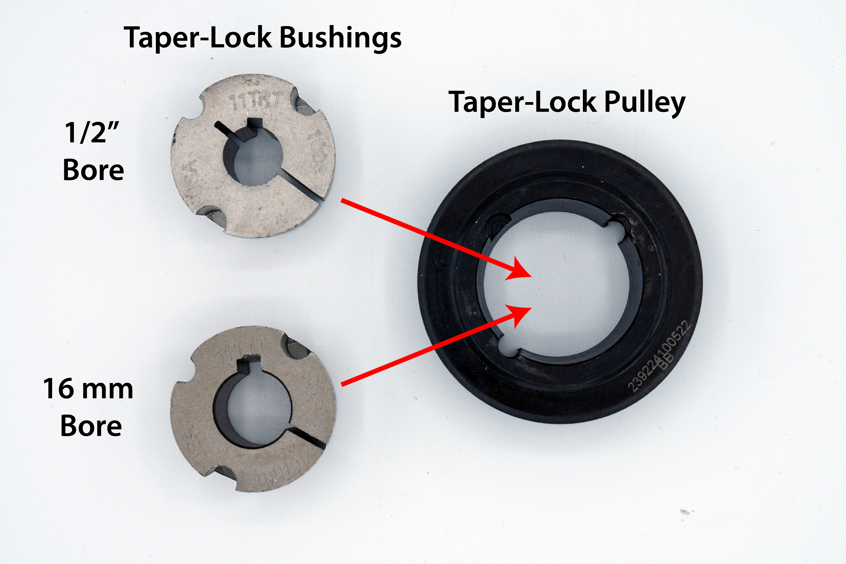
When working with import products that abide mostly by metric standards in the United States, it can be difficult to find compatible pulleys with IDs for both metric and U.S. customary shafts. Such was the case for finding two pulleys that fit the new Y551’s 7/8” shaft and the spindle’s 40 mm shaft. Further, the stock spindle pulley was held onto the shaft through tiny M3 set screws. I am not a fan of set screws because they damage the surface they are biting into and can lose their holding power when vibrations cause them to back out. A gear puller is often required to remove these pulleys as they must slide over the mushroomed surface created by the set screw.
Taper-lock pulleys solve the mismatch in units between shafts problem and do not cause damage during installation. A taper-lock pulley is an assembly consisting of a bushing that sits inside of a pulley. The bushing has an ID that matches the shaft’s OD and a tapered outside geometry that matches the pulley’s bore. A slit through the wall on one side of the bushing causes the inside diameter to decrease as it is pressed into the taper of the pulley, effectively clamping down on the shaft. The bushing is seated into the pulley through two screws. This two component design allows one pulley to be compatible with a range of shaft diameters as long as there is an appropriate bushing. B&B Manufacturing sells a bushing for nearly any shaft size under the sun. If they don't have the size you need, then they will make you one.
To accommodate both small and large shafts, bushings come in several different outside diameters. The smallest bushing is a 1008, which is compatible with 1/2” to 1” (12 – 25 mm) shafts, and the largest is a 7060, which is compatible with up to 7” (178 mm). It is important to note that a taper-lock pulley is only compatible with one style of bushing. The larger the bushing, the larger the pulley will have to be. This leads to the one downside to the taper-lock system, which is that the pulley may have to be quite large to accommodate the bushings. For example, the smallest pulley for the 1008-style bushing still has an outside diameter of 2.1” (53 mm). This prevents low tooth-count pulleys from being compatible with the taper-lock system.
Below are the taper lock pulleys that I used for the spindle and z-axis, which both rely on a belt. Of course the bushing diameters will change depending on your spindle and ball screws.
| Connection | Shaft 1 ⌀ | Pulley 1 | Shaft 2 ⌀ | Pulley 2 |
|---|---|---|---|---|
| Motor to Spindle | Motor 7/8" | 36T Poly Chain | Spindle 40 mm | 36T Poly Chain |
| Z-Motor to Z-Screw | Motor 16 mm | 18T L-Series | Ball Screw 1/2" | 18T L-Series |
Lubrication
If your benchtop mill has steel-on-steel or even steel-on-polymer (e.g., Turcite/PTFE) ways, then oil lubrication is necessary to prevent damage to the machine. While some “premium” benchtop mills are sold with manual or automatic one-shot oilers, these systems typically only lubricate the ways. The stock lead screws require manual application of grease or oil. CNC milling machines will experience faster and more frequent linear motion compared to a manual instrument and as such running oil lines to the ball screws is an important part of the CNC conversion process.
Please note: While EP 0 grease or similar may be the preferred way to lubricate a ball screw, a separate automatic greaser would increase the cost and complexity of the lubrication system. I have had no issues thus far with using the same oil for both the ball screws and ways on my benchtop mill.
Way Oil Types
Way oil is formulated to include additives that prevent corrosion and provide some “adhesiveness” so that oil does not readily drain out of the ways or ball screws. Way oils are commonly sold according to an ISO standard based on their viscosities:
- 32 mm2/s is suitable for horizontal ways on small to medium size machine tools. Product: Mobil Vactra No. 1
- 68 mm2/s is suitable for horizontal ways on small to medium size machine tools. Product: Mobil Vactra No. 2
- 120 mm2/s is suitable for vertical ways and large machines where pressures are high. Product: Mobil Vactra No. 3
- 220 mm2/s is suitable for vertical ways and large machines where pressures are high. Product: Mobil Vactra No. 4
Mobil Vactra oils No. 1-4 can be used not only for linear ways but also for ball screws. For small benchtop mills Mobil Vactra No. 2 (68 mm2/s) is preferred but any of the Mobil Vactra Oil Numbered Series can be used depending on availability.
Lubrication Manifolds, Tubing, & Fittings
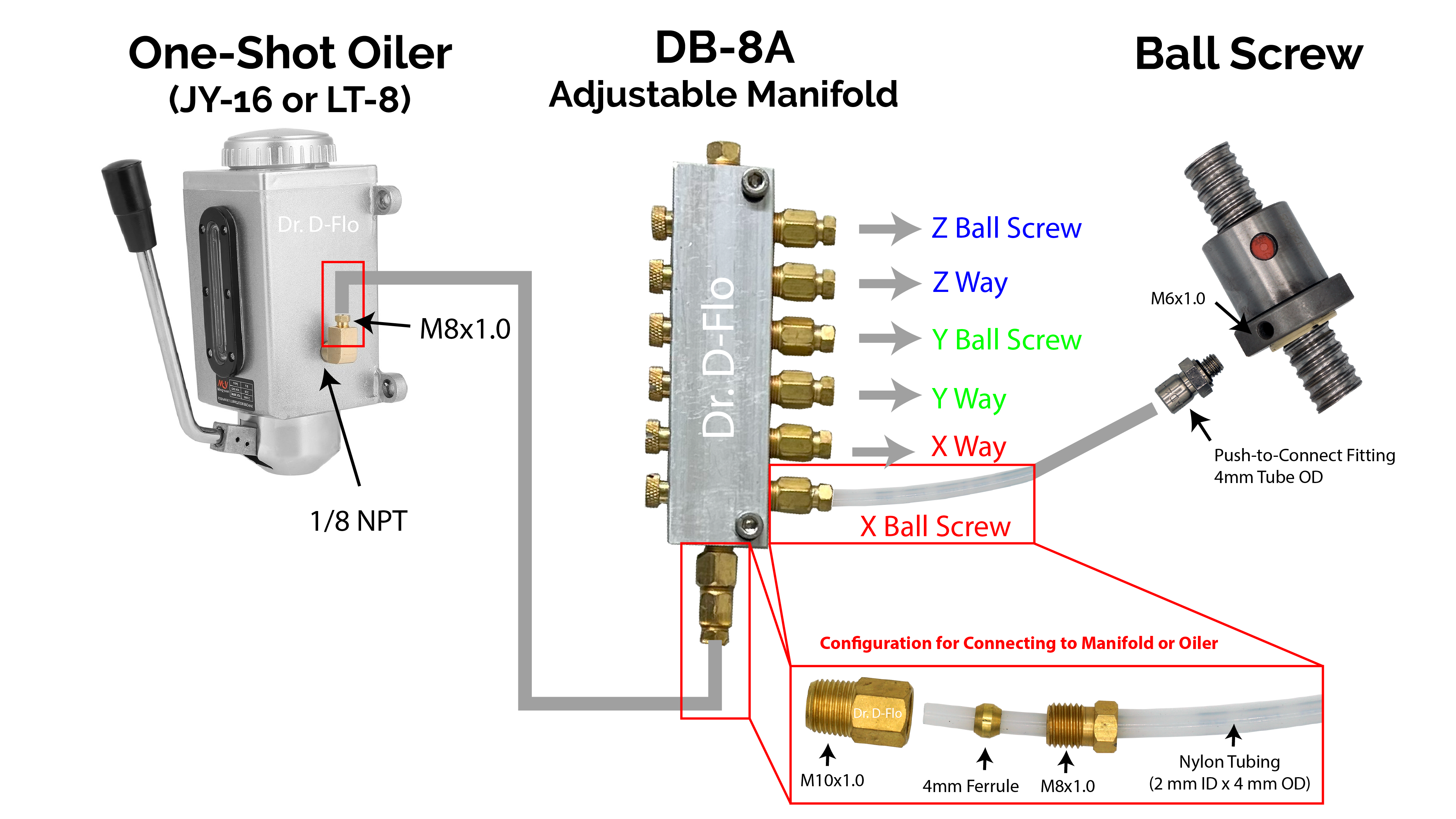
Another issue with the stock lubrication system on most import mills is that the distributor manifold, which sends oil from the one-shot oiler to the separate ways, is not adjustable. Therefore, oil will preferentially flow through the outputs of least resistance. With this setup, the X- and Y-ways will have excess lubricant as the oil does not have to fight gravity to reach them, while the Z-way runs dry. To combat this, an adjustable manifold, such as the DB-8A from SuperCrown should be used. Please Note: an output on the manifold is required for each surface/screw being lubricated. This is typically 6 (3 ways and 3 ball screws).
To connect the adjustable manifold to the ball screws two sets of fittings and an oil line are required. Stock lubrication systems usually deliver oil through 4 mm OD aluminum or flexible stainless steel mesh lines. While durable, these materials are difficult to work with for the DIYer and nylon tubing is preferred due to ease of installation.
Standard 2 mm ID by 4 mm OD tubing is compatible with most fittings. The recommended DB-8A manifold comes with the ferrules and compression sleeves required to connect to this size tubing, but a compression fitting will need to be sourced for each ball screw. Import ball screws typically use an M6 x 1 mm thread for the lubrication port and are compatible with these straight and right-angle fittings.
Electronics
I also want to point out that I am NOT an electrical engineer or liscensed electrician. If you have a safety concern with any of the information provided in this guide please email me directly at [email protected], so that I can make the appropriate changes. With that said, I accept NO liability for any harm or loss resulting from following this guide. Proceed at your own risk.
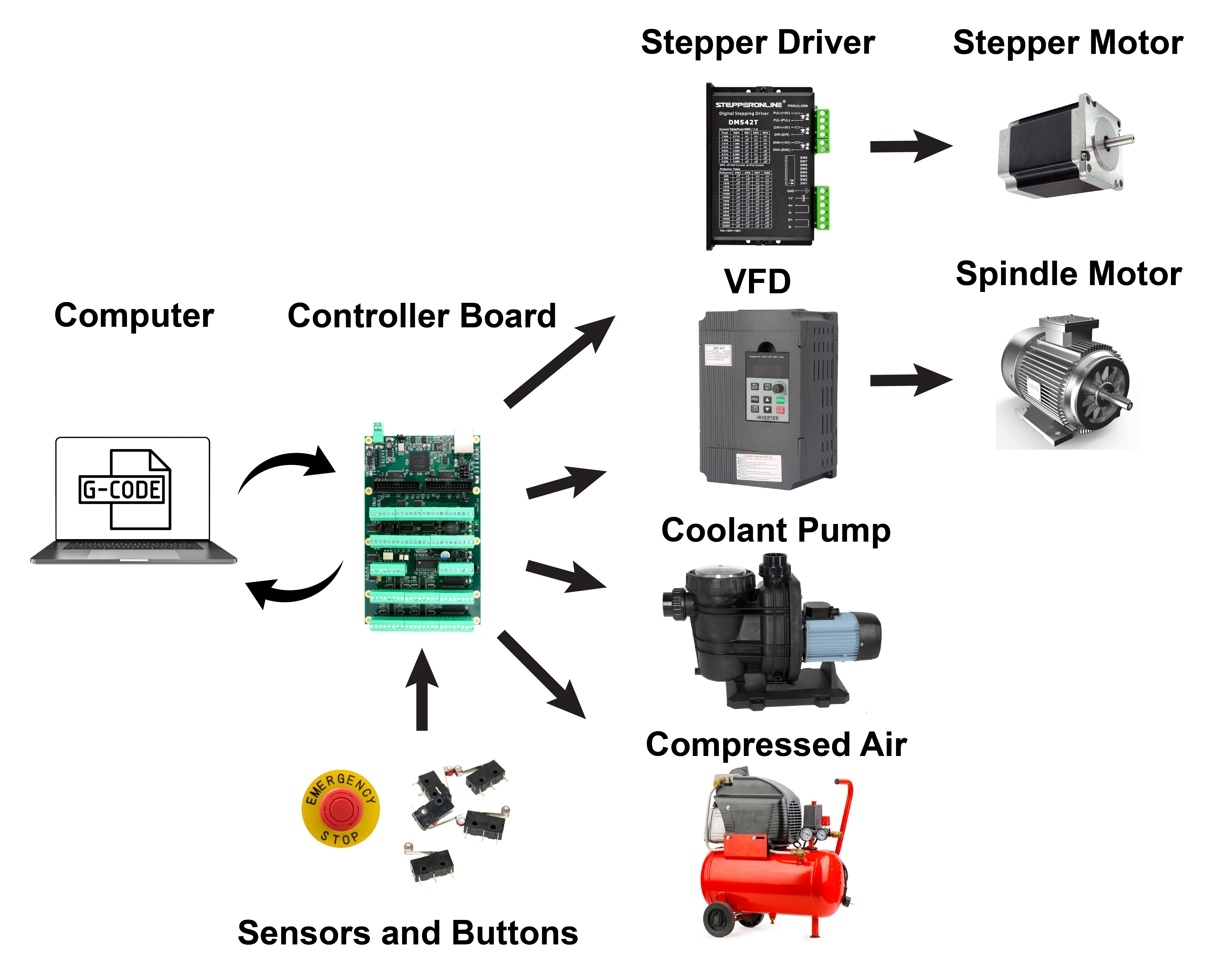
A Computer Controlled Milling Machine
Nearly every aspect of the milling process can be computer controlled. Entry level CNC mills will have computer controlled linear motion (e.g., stepper motors) and homing switches. More sophisticated mills will have probes for finding the location of the stock material, solenoids for controlling compressed air and coolant, automatic tool changers, and many sensors that monitor the cutting process. All of these industrial features can be added to your CNC mill build, so really the only limit the budget budget.
I have built my mill in phases. The first configuration was relatively simple and cheap. The mill had three stepper motors, three limit switches, a tool length probe, a work offset probe, and handheld pendant for jogging the axes. After a year, I upgraded the stepper motors to servo motors and added a power draw bar to quickly swap in and out tools. My most recent upgrade focused on adding rigid tapping, where the mill knows exact the spindle orientation for precise helical moves. This upgrade required a new vector duty motor, SVC VFD, and an encoder. If you are new to CNC mills, then start simple as I did and add features over time.
LinuxCNC
LinuxCNC is a feature rich software for running your mill. It can be configured to not only control 3-axis mills, but also 4- and 5-axis machines as well as lathes, robotic arms, and really anything with motors on it. The software is completely free and receives consistent updates. However, the downside of choosing LinuxCNC as your control software is that it is difficult to program, and you must rely on forum post for help. I will walk you through how I set up my configuration files, but keep in mind that you can always opt for a more user-friendly (but more expensive) control system such as those offered by Centroid.
There are two requirements for a LinuxCNC control sysem: 1) A computer running Linux and 2) A controller board connected to the computer that interfaces with the motors and sensors. This website is a great resource for installing all the different flavors of Linux with real time extensions. The real time extensions will allow LinuxCNC to operate largely uninterrupted, which is critical because CNC motion has strict timing requirements. There are two types of real time extensions: RTAI and Preempt-RT (uspace). The RTAI extension is for controller boards that use either a parallel port or PCI for communication with CNC hardware, and the Preempt-RT (uspace) extension is for setups that use a parallel port, PCI, or ethernet. This guide will use the Preempt-RT (uspace) because we will be using a Mesa board connected by ethernet. More on this later. Please note: the RTAI extension has less latency (see latency section below) and may be a good option if you are using a PCI board or parallel port.
If you are new to Linux, then a lot of the terminology may seem overwhelming. I recommend installing Debian 9 – follow these instructions and then installing Linux CNC 2.8 – follow these instructions. Debian 9 has backwards compatability for all the old dependancies of LinuxCNC, and I have found stock LinuxCNC to work out of the box with this OS. If you plan on using Probe Basic GUI, which is what I use, then you will need Debian 10 - follow these instructions.
Which Computer?
Latency
But what computer should you use? Is a fast multi-core CPU required? No. In fact, raw CPU power is really not that important. Low-end Atoms and Celerons CPUs are more than sufficient for running LinuxCNC. Typically a computer is selected based off its latency. Latency is defined as “how long it takes the PC to stop what it is doing and respond to an external request.” With LinuxCNC, the computer’s CPU handles the step pulses (in some cases – see below), so any delay (i.e. latency) between when a step pulse needs to be generated and when it is actually generated will directly affect the motor's performance. A computer's latency is a sum of all the delayed caused by active components.
Because latency is not a specification that is reported by manufactures, I believe that it is best to purchase a computer that other have had success with. I had a lot of luck with both the Intel Nuc 5 (i3 CPU) and Intel Nuc 11 (i5 CPU). There is a database of the realtime performance of various computers/CPU found here.
It may be helpful to point out what computers are not ideal for running LinuxCNC. Laptops are rarely a good fit. All of the power management software that is running in the background to prevent the laptop from overheating eat into the realtime performance. There is more information on what hardware is not ideal for LinuxCNC found here.
With the correct microcontroller, latency is not as important.
This may seem contradictory to the last section, where I preached minimizing latency, but the above advice is most important for older controllers that rely on a feature known as software stepping, where the CPU directly generates the step pulse. In this setup, faster CPU response times equals higher step rates.
Today, most controllers that are paired with LinuxCNC have a hardware step-generator. With this feature, the CPU only has to send over a step frequency (velocity of the movement) and a direction. The hardware on the microcontroller handles generating the step pulses, and thus, the CPU only has to handle changes in gross movement.
Now before you go grab that old laptop with terrible latency, just know that really high latency values can still affect the performance, so I still recommend taking latency seriously and reducing it in any way possible.
Controllers with hardware step-generators will be discussed below.
How to measure latency
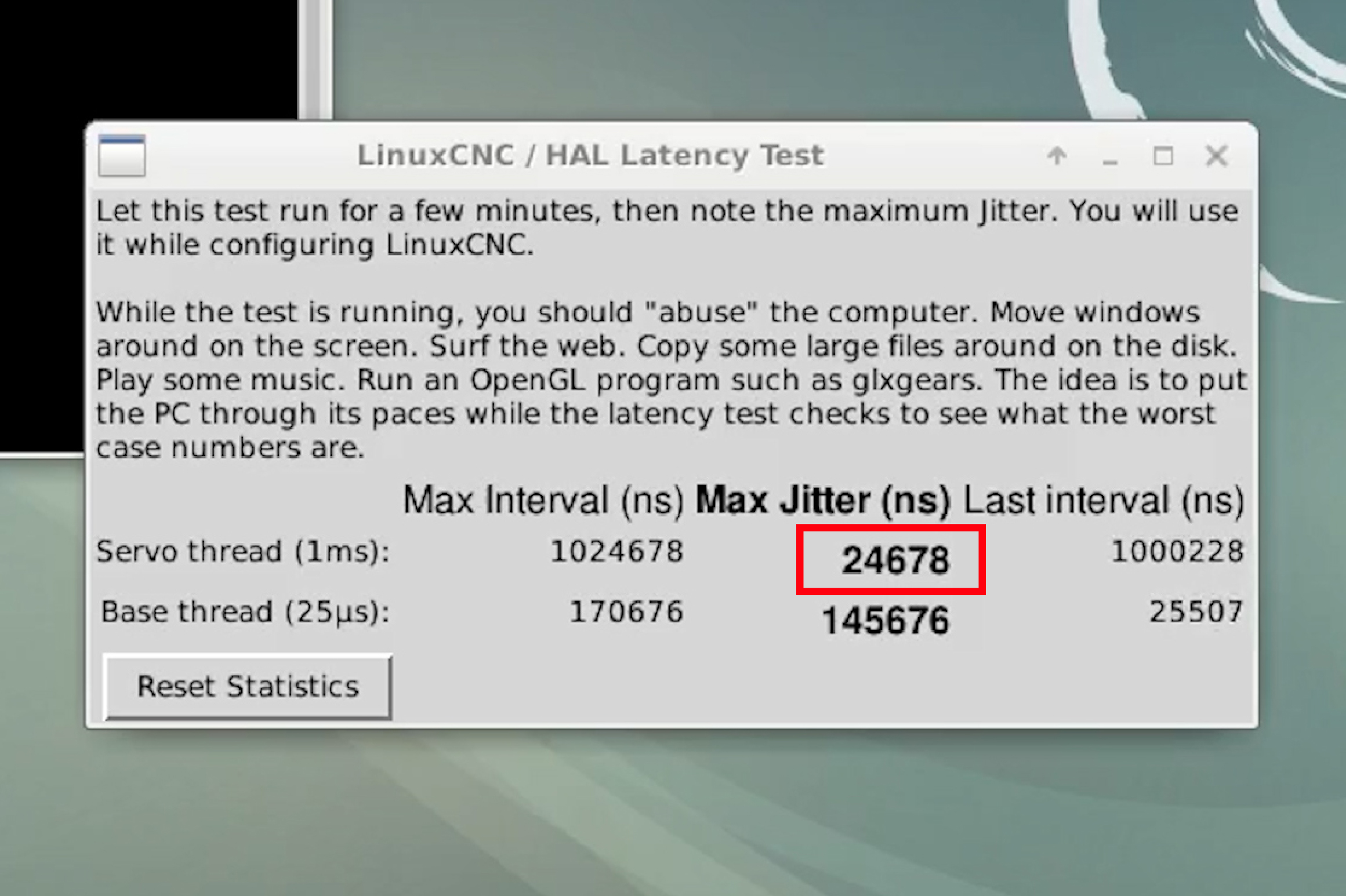
Once Linux and LinuxCNC is installed, go to the terminal and type:
latency-test A window will pop up with some changing values (Figure 2). If the board that you select uses a hardware step-generator (very likely), then you only need to concern yourself with the Max Jitter for the Servo thread. Compared to the base thread, the servo thread is for components that can handle slower response times. Remember with hardware step-generation the CPU doesn’t have to handle the pulses, so it does not need to be as responsive. This is a good thing. With software step-generation you have to measure latency according to the base thread, which can be fussy and requires a very low max jitter value for proper step-generation.
The max jitter for the servo thread at idle is not very helpful. When controlling the mill the computer will have its hands full. Intuitively, the more tasks the computer is completing the longer it will take to respond to a request (higher latency). This is a little bit of an oversimplification because your computer should be running the Real-Time version of Linux, which in theory should have the same latency regardless of what it is doing. However in practice, more activity does increase latency. So for proper results, you should stress your computer by moving windows around, transferring files from an flash drive, and really anything else that “distracts” the computer. The latency test needs to be run for at least 10 minutes.
For optimal performance you want a max jitter <100ns. However, there have been reports on the forum that value up to 300ns will work, but you might encounter following error.
How to improve latency
In many cases, Latency can be drastically improved by disabling non-mission critical features in the bios, such as:
- Wifi
- Hyperthreading
- Turbo boost/speed options
- Any cool and quite modes
- Power saving options
Turn off each of these features one at a time and re-check the latency.
If you plan on sending G-code files over to the mill via the cloud, then not having wifi would be a pain. If you determine that the internal wifi module is a source of latency (like it was for me), then you can purchase a wifi usb dongle, which should not add latency.
Linux CNC Controller Boards
The controller board is the bridge between the computer and the CNC hardware (e.g. the stepper drivers, limit switches, coolant pumps, etc.). LinuxCNC can communicate with the controller over PCI, PCIe, and Ethernet. USB is not an option for LinuxCNC because it introduces a significant amount of latency.
Mesa Boards
The most popular controller boards paired with LinuxCNC are Mesa’s FPGA cards. FPGA is an acronym for Field-Programmable Gate Array, and basically, the logic of these semiconductors can be reprogrammed after being manufactured (in other words, can be programmed out in the “field”). Simply put, Mesa’s FPGA cards are extremely flexible and can be molded to fit specific applications like running a mill, lathe, or a multi-axis robotic arm.
Mesa offers cards that communicate with Linux over both PCI/e (5i25 or 6i25) and ethernet (7i76e). Which is better PCI/e or ethernet? In theory, you can use the RTAI extension with the PCI/e boards and achieve lower latency, but remember latency is not as important for these boards because they have hardware step-generation. The downside of the PCI/e boards are that you need a full size computer with a PCI/e slot. For this reason, you can’t use a small form factor PC (e.g., Intel Nuc) or an all-in-one with a PCI/e card. Further, the PCI/e cards need to be combined with the 7i76 (not to be confused with the 7i76e) daughter board to get IO needed for the stepper/servo drivers and peripherals.
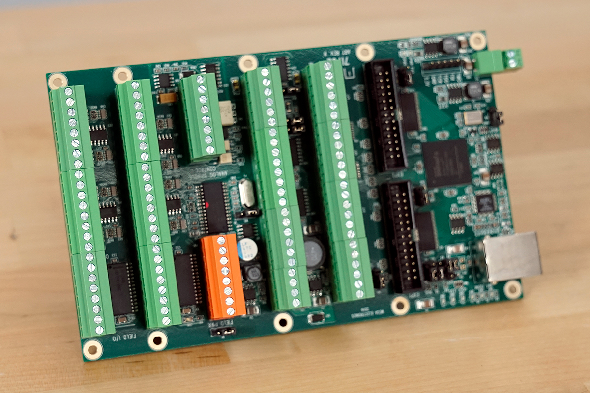
I went with the 7i76e (Figure 3) because of the compatibility of the small form factor computer and because ethernet cables and connections are ubiquitous. It was easy to find panel mount to bring the ethernet cable into the electrical cabinet, where the 7i76e was mounted.
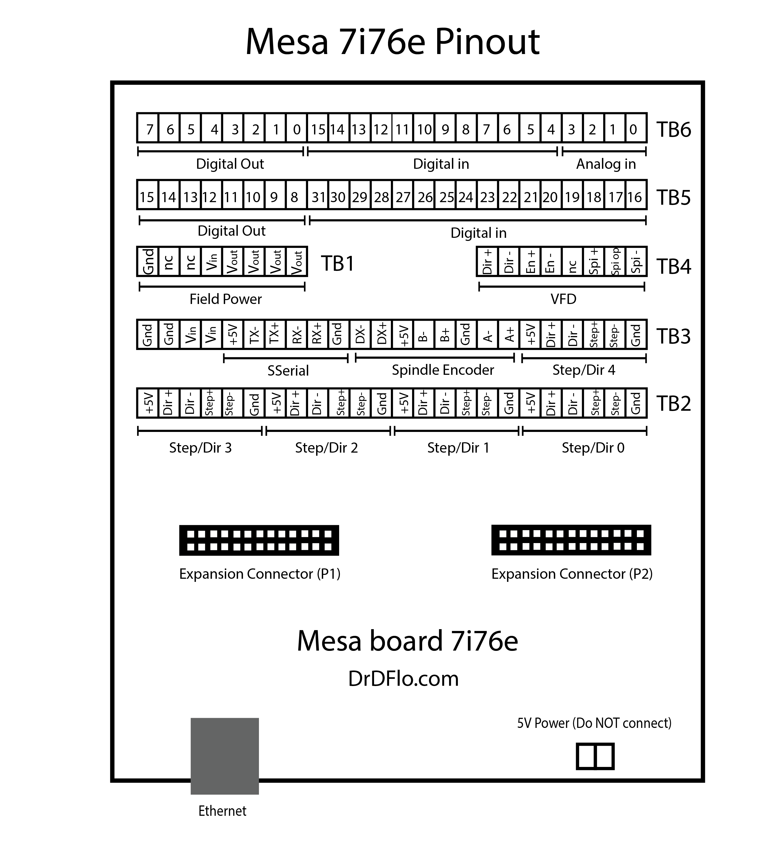
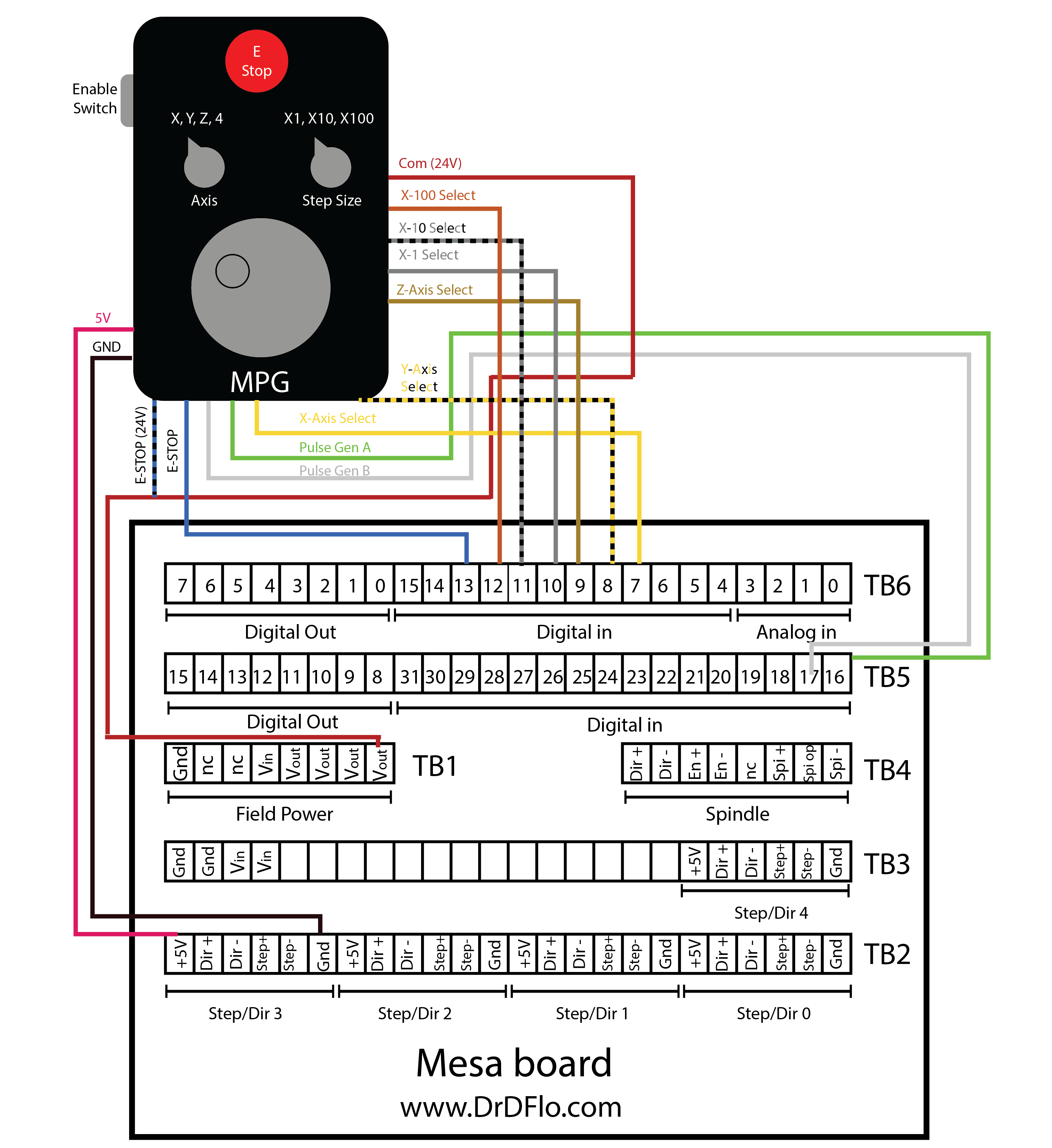
Unfortunately, the documentation for the Mesa cards is not written for a layman. This includes the manual for the 7i76e. A user over on the LinuxCNC forum posted the pinout for the 7i76e board, which helped in making the following diagram (Figure 4) as well as understanding the role of all the different jumpers on the board.
Wiring
Disclaimers:
Electricity is dangerous. Mistakes can cause injury and be expensive. Find out how to work on electrical components safely...Connecting components to the Mesa 7i76e
You can click through the tabs below to see how I wired up different components to the Mesa 7i76e. I included some tips like how to wire an NPN vs PNP switches to the Mesa board and what is going on with all the different jumpers.
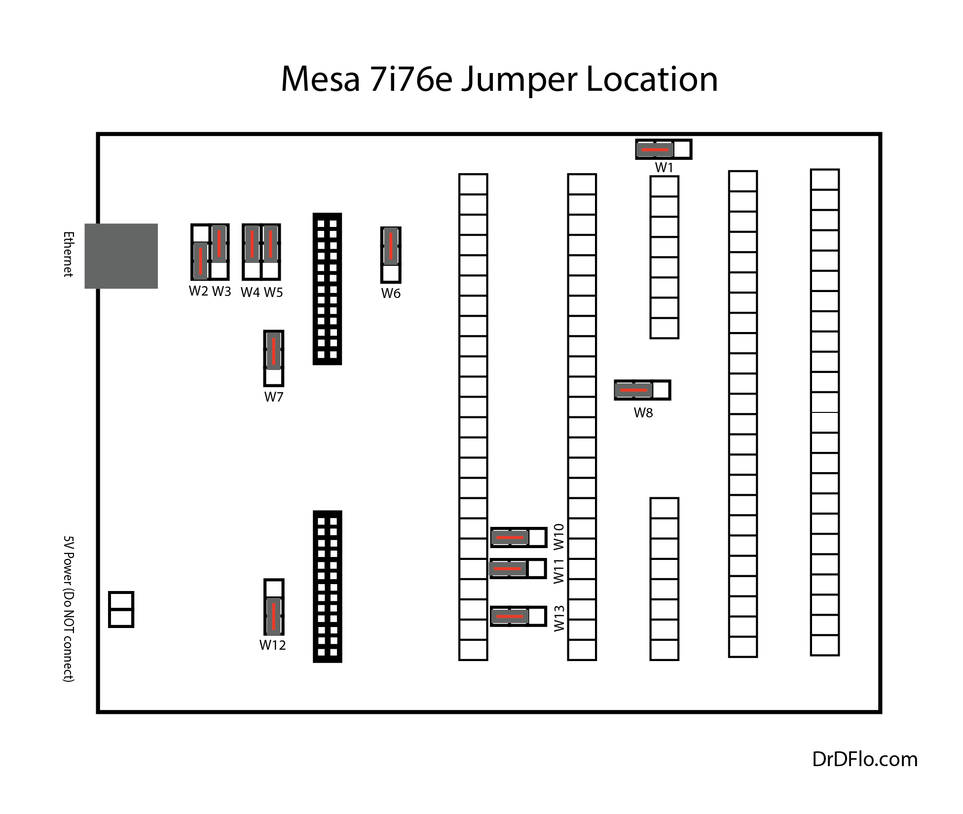
The 7i76e has 13 jumpers that handle an array of settings from the pullup voltage to the IP address of the board. Study the diagram (Figure 3) below and adjust the jumpers of your board to match. Jumpers W7, W10, W11, and W13 differ from the default jumper configuration. Make sure your board matches the orientation of the schematic below (ethernet port is on the left).
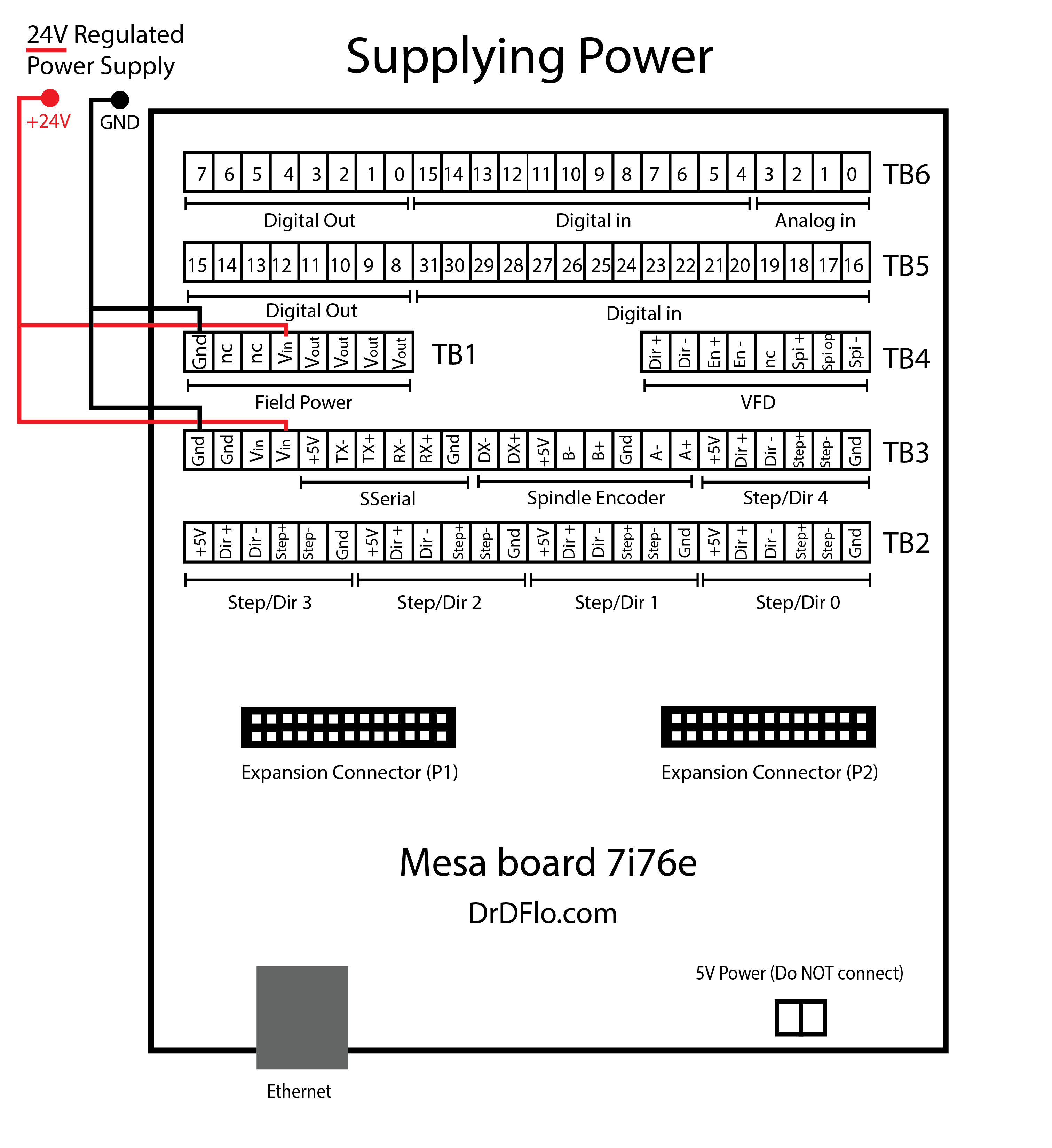
The Mesa board requires a 10-32V field power source. 24V is recommended and is what is shown in the diagram below (Figure 4). With the W1 jumper in the left hand position, the field power with power the logic of the board, so you do NOT and should NOT connect 5V power to the terminals near ethernet connection (marked on the board).
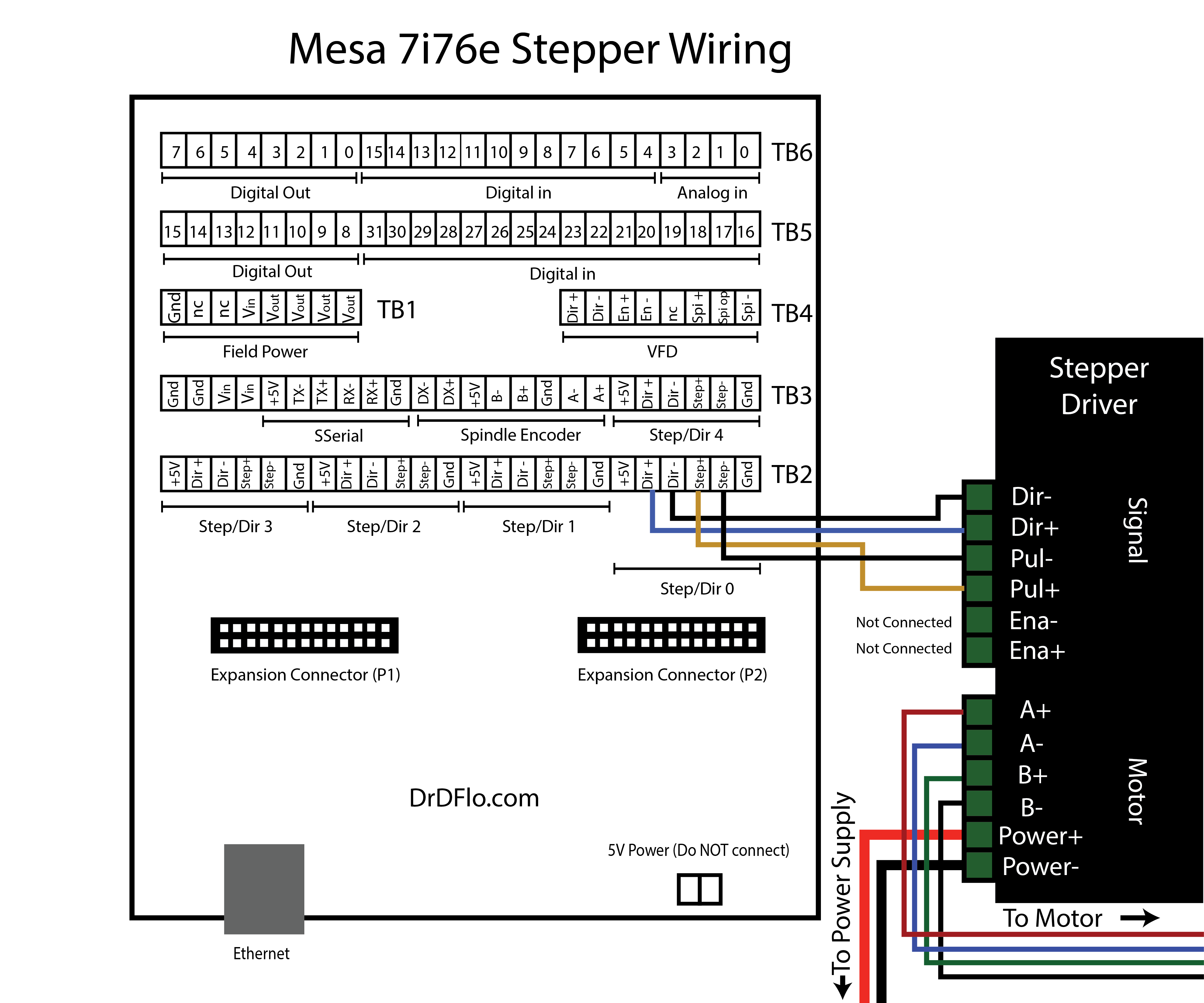
Fortunately, wiring up stepper drivers to the 7i76e is rather easy. You just connect the step/pul and direction pins (both + and -) to the corresponding terminals on the stepper driver.
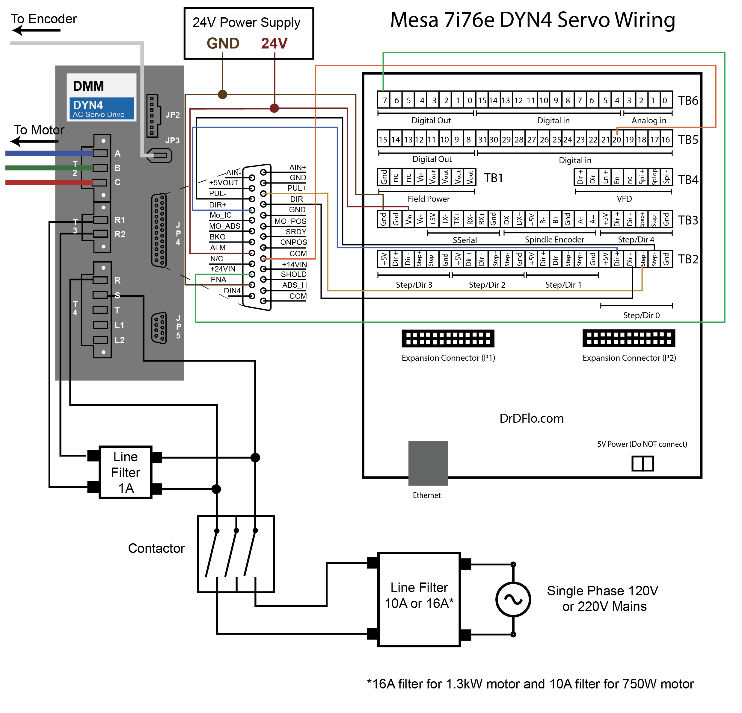
To acess the signal pins on the DYN4 drive, you will need a DB25 connector (not supplied).
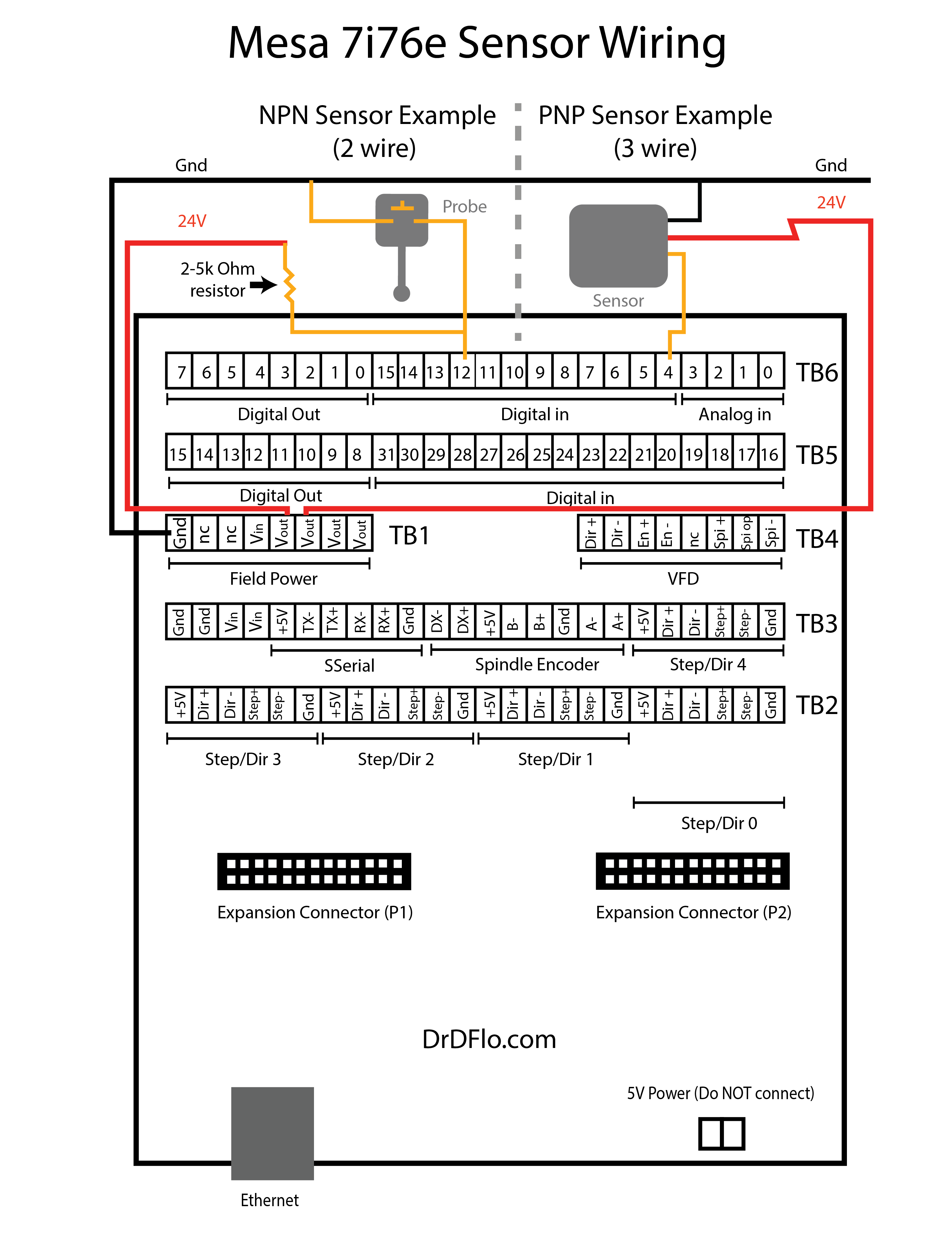
There are many reasons why you might want to wire up a sensor to the 7i76e. Limit switches are an obvious example but probes that set the tool length and work offsets are also sensors. There are two different types of sensors: NPN and PNP. I recommend reading this post if you have never heard of these acronyms before. The 7i76e has sinking inputs, which means the input is triggered when a positive voltage is applied, and therefore PNP-type sensors can be directly wired to the board. NPN sensors, on the other hand, require a pullup resistors to the positive voltage source. Almost all probes are NPN, so be sure to include this pullup resistor or else the 7i76e will fail to recognize when a probe has bumped into a tool or an edge of stock material.
A handheld pendant is a convenient way to jog each axis of the mill. It speeds up every task from when you first need to tram the mill to setting work offset prior to machining a part. I would also say that it is the safest way to move the spindle/table because you can keep your eye on the mill while moving the handwheel.
The handwheel is a Manual Pulse Generator (MPG). The 7i76e can accept input from two MPGs. However, most commercial handheld pendants have a single MPG and a switch to select which axis is jogged when the hand wheel is rotated. . To accept the MPG input, the 7i76e has to be placed in “Mode 2,” and the digital input pins 16-19 will accept the encoder signal from the MPGs. The software section (below) will show you how to change the mode of the 7i76e when editing the configuration file.
Carefully study the wire diagram below because it corresponds with most universal MPGs that are sold on Amazon and eBay. If you want the exact pendant that I used then check the bill of materials above. Make sure that you don’t purchase a USB pendant because as far as I know those models won’t work with LinuxCNC and even if they did work that would defeat the purpose of the real time performance of LinuxCNC.
If your MPG has four wires, for example: A, B, A’, B’, you can ignore the A’ and B’ because the Mesa board only allows two inputs per MPG. A and B are sufficient for direction and movement. If your curious, I believe that A’ and B’ act as a differential pair, which could be used to subtract noise out of the signal. However, the 7i76e is not setup to convert a differential pair into single-ended logic.
Ethernet Connection
This section will be a quick guide to connecting the Mesa 7i76e over ethernet. This process can vary based on the Linux OS and the ethernet adaptor that is being used. The steps below are numbered for organizational purposes, but they do not need to be followed in order.
1. The default IP address of the Mesa 7i76e is 192.168.1.121. To avoid IP address overlapping, it is recommended to set the address of the 7i76e to 10.10.10.10 by setting the W3 Jumper to up and W2 Jumper to down. This was illustrated in Figure 3. After changing Jumpers, the board must be power cycled.
2. Next the static IP address on the host computer must be set to include the 7I76E's new IP address in its masked range. This takes a couple steps (labeled alphabetically):
2a.) Determine the name of your local ethernet by typing the following in the command terminal:
ip aThe local ethernet name will look something like the following: eth0, eno1, or enp0s7. Write this down.
2b.) Open the network interfaces file by navigating to /etc/network/ and open the interfaces file via your file explorer or terminal. Add/change the text in this file to conform to the code below. Eth0 will be replaced by the name of your computer's local ethernet name.
# This file describes the network interfaces available on your system
# and how to activate them. For more information, see interfaces (5).

source /etc/network/interfaces.d/*

# The loopback network interface
auto lo
iface lo inet loopback

# Ethernet interface naming scheme has changed over the years
# Replace: eth0 with your computer's local ethernet name
auto eth0
iface eth0 inet static
address 10.10.10.1
netmask 255.255.255.0

#If you have an Intel ethernet controller, disable IRQ coalescing
hardware−irq−coalesce−rx−usecs 0
3. Ping the Mesa board by typing the following in the terminal:
ping 10.10.10.10Receiving a response means that you have correctly configured the network settings. Hooray! The first ping will have the longest response time, but each subsequent ping should be under 0.1 ms for optimal communication with the board. Response time >0.2 ms will cause problems. If you are using an Intel ethernet controller, then disable IRQ coalescing in the interfaces file. See example code above.
4. In your HAL file (this has not been introduced yet, see below), the IP address of the board will need to be updated:
loadrt hm2_eth board_ip="10.10.10.10" config="firmware=hm2/7i76/7i76e.BIT num_encoders=1 num_pwmgens=0 num_stepgens=3 sserial_port_0=2xxxx"5. It seems that this ethernet connection process changes with LinuxCNC updates and new ethernet chips and drivers. This short guide may not work for you for this reason. For up-to-date information, I recommend reading this thread over at LinuxCNC forum (update: If you are using Debian 10 Buster then click that link).
LinuxCNC Configuration Files
I’m more of a hardware guy, so learning how to adapt LinuxCNC to my custom milling machine was definitely a challenge. The amount of information that is available on the LinuxCNC Wiki is overwhelming, but I strongly recommend putting the time in upfront and reading through as much of this documentation as possible because it will save you a lot frustration when setting up the software side of your mill.
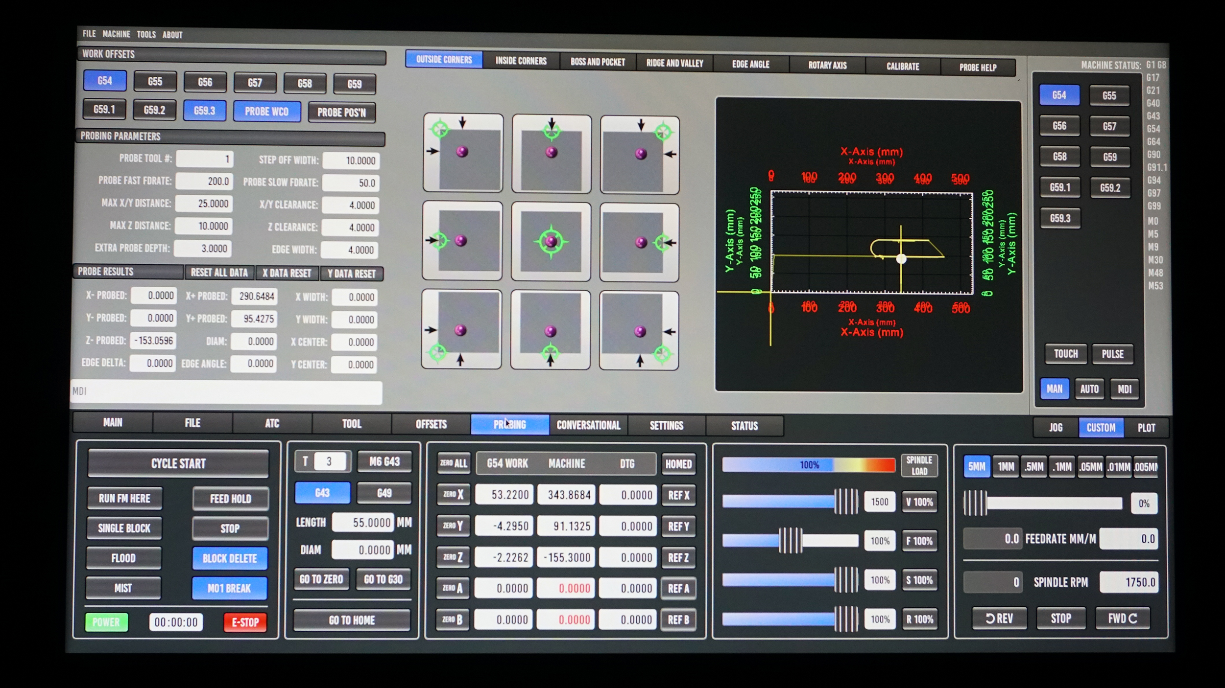
Picking a GUI: Probe Basic
LinuxCNC has different graphical user interfaces (GUIs) with some being more optimal for touch screens and others giving the user access to complex probing macros with a push of the button. There is not going to be a performance difference between the different GUIs, but some designs result in higher productivity than others. My favorite GUI is Probe Basic (Figure 10). Probe basic is the only LinuxCNC GUI that looks like it is from the 21st century, and it doesn’t just have the looks. It is chalked full of probing subroutines that allows you to accurately set the work coordinates with a push of a button. Here is a list of some of the other GUIs that are avialble.
GUIs require different packages to be installed and may require a special distribution of Linux, so I recommend picking out a GUI prior to installing LinuxCNC.
Download, Install, and Setup LinuxCNC
If you are going to use Probe Basic as your GUI of choice then you can follow the full installation instructions provided by the Probe Basic team found here. If you are using a different GUI and/or prefer a different Linux operating system, like Mint or Ubuntu, then follow instructions found here.
If you are using a Mesa ethernet card, then after installing OS and LinuxCNC it is very important to configure the network adapter to get along with the Mesa card. Configuring the network adapter is slightly different process for Debian 9, Linux Mint 19, and Lubuntu 19.04. This is a very important step - do not forget!
Run the Mesa Configuration Wizard
The Mesa boards and LinuxCNC go together like peanut butter and jelly. The best example of this compatibility is the Mesa Configuration Wizard that is automatically installed when LinuxCNC is installed. The Mesa Configuration Wizard is better known as PNCconf. A great step-by-step guide for how to use PNCconf is found on the LinuxCNC website. You can test your latency and motor wiring in PNCconf. Try and fill in as much information about your CNC machine into the configuration wizard as possible. Use the 7i76e wiring diagrams I made above to accurately tell PNCconf which components (stepper motors, limit switches, etc.) are plugged into which pins. Next I will go over how to customize the files that are outputted by PNCconf to match the LinuxCNC configuration files exactly to your mill’s setup.
After completing PNCconf, there will be new folder located in your LinuxCNC/configs folder. This folder, named after your mill's configuration, will contain a couple different files but the HAL and INI files are the most important.
Tweaking the HAL File
The Hardware Abstraction Layer or HAL file is the most intimidating file for those who are new to LinuxCNC. While the Mesa Configuration Wizard gets you pretty close to a completed HAL file, manual edits are needed if you are looking to add complex features to your CNC mill like a jog pendant or multiple probes (e.g. work and tool probes).
I am not going to pretend like I fully understand the intricacies of the HAL file. I have yet to finish reading the 100 page manual on how the HAL file works and all of its components. Everything I know has been from trial-and-error, so it may not be 100% accurate (just a heads up).
In my eyes, the main role of the HAL file is to act as a link between hardware and digital components. For example, let’s say you have the limit switch for the X-axis plugged into digital input pin 4 on the Mesa board. How in the world will LinuxCNC know that? Well, that information is defined in the HAL file, and it looks like this:
net home-x <= hm2_7i76e.0.7i76.0.0.input-04-notThe net command creates a connection between the Mesa pin, which is input 4 in this example, and the digital X-axis limit signal (home-x). This is the limit switch that will be triggered when the mill is instructed to home, which is why it is home-x. The "<=" syntax is optional, but it makes the code easier to read. Following input-04 the word "-not" inverts the signal. This limit switch is normally connected (NC), and therefore input-04 will be at 24V until the limit switch is tripped. Therefore, when input-04 is not connected to 24V the limit switch has been tripped (i.e. home-x should be true).
Setting up a probe is just as easy as setting up a limit switch:
net probe-in => motion.probe-input <= hm2_7i76e.0.7i76.0.0.input-20Here we have tied together three items: 1. the probe-in signal, 2. the state of the input-20 pin, and the digital motion.probe-input pin. During a probing move if the state of input-20 changes from false to true then so will the motion.probe-input, which signals to LinuxCNC that probe has been tripped during a move.
While setting up one probe was somewhat trivial, connecting two probes (tool height probe and work offset probe) is a trickier example because LinuxCNC only recognizes one probe signal. There is not a probe-in-2 signal. This isn’t a huge deal because we will never use both probes at the same time. You could wire both probes to one input and then net that single input from the 7i76e to the probe signal in the HAL file. However, there can be issues with this approach depending on the type of sensor/switch the probes act as. In the HAL file we can connect two inputs to the single probe signal digitally through an or2 component. The or2 component takes input from two pins (say from a work probe and tool probe) and outputs a true/false value similar to how or statements are used in other programming languages like Python. If either the work or tool probe input is true, then the output of the or2 will be true. The output of the or2 can then be connected to the probe signal via a net. To initialize the or2 component you have to both load the component by using a loadrt command and add it to the "thread" so that the component is updated (i.e. constantly checking for changes in the state of the inputs) through the addf command. The loading and adding commands precede the use of the or2 function. This can be a little confusing. I had to read the Basic HAL Tutorial a couple of times before everything clicked. Below is everything written out.
loadrt or2 [count=1]
addf or2.0 servo-thread

or2.0.in0 <=hm2_7i76e.0.7i76.0.0.input-20
or2.0.in1 <=hm2_7i76e.0.7i76.0.0.input-21

net probe-in => motion.probe-input <= or2.0.out
This definitely looks more complicated than the previous probing example, but I hope it makes sense. Notice the .0 in the or2.0. If you need another or2 component later on then you will have to load and add another or2 statement, which is accomplished by modifying the top code code to:
loadrt or2 [count=2]
addf or2.0 servo-thread
addf or2.1 servo-thread
Your next use of or2 will be or2.1. Don't forget: in computer programming counting starts at 0!
Configuring MPG Jog pendant in HAL
One of the hardest parts of this entire build was configuring the HAL file to read the inputs from a pendant with a jog wheel. All of the HAL examples online did not seem to work with my setup, which was very frustrating. However, after I got everything set up the pendant has worked flawlessly. I hope my code, which is below, speeds your build along! Read through it and the inline comments then I will discuss how it works below.
# sserial_port_0 needs to be set to 2xxxx. This changes the 7i76e to Mode 2
# and allows it to accept two seperate MPG inputs on pins 16/17 and 18/19
loadrt hm2_eth board_ip="10.10.10.10" config="firmware=hm2/7i76/7i76e.BIT num_encoders=1 num_pwmgens=0 num_stepgens=3 sserial_port_0=2xxxx"

# The mux4 component will be used to switch jog increment
loadrt mux4 count=1
addf mux4.0

# --- MPG ---
# In linux 2.8 "joints" (i.e. your motors) and axes (your directions x, y, z) are seperated.
# However, for my simple three axis mill with one motor per axis this is not particularly
# useful. We need to tie the joints to the axes (joint.0 = axis.x, joint.1 = axis.y,
# and joint.2 = axis.z)

# When jog-vel-mode is set to 0 the axis will move jog-scale
# When jog-vel-mode is set to 1 the axis will stop when the
# handwheel stops turning

setp joint.0.jog-vel-mode 0
setp joint.1.jog-vel-mode 0
setp joint.2.jog-vel-mode 0

setp axis.x.jog-vel-mode 0
setp axis.y.jog-vel-mode 0
setp axis.z.jog-vel-mode 0

# This sets the scale that will be used based on the input to the mux4
# This mill reads in metric units so jog scale is 1mm, 0.1mm, and 0.01mm
setp mux4.0.in0 1
setp mux4.0.in1 0.01
setp mux4.0.in2 0.1

#The inputs to the mux4 component
net scale1 mux4.0.sel0 <= hm2_7i76e.0.7i76.0.0.input-10
net scale2 mux4.0.sel1 <= hm2_7i76e.0.7i76.0.0.input-11

#The output from the mux4 is sent to each axis jog scale
net mpg-scale <= mux4.0.out
net mpg-scale => joint.0.jog-scale => axis.x.jog-scale
net mpg-scale => joint.1.jog-scale => axis.y.jog-scale
net mpg-scale => joint.2.jog-scale => axis.z.jog-scale

#The Axis select inputs
net mpg-x joint.0.jog-enable <= axis.x.jog-enable <= hm2_7i76e.0.7i76.0.0.input-07
net mpg-y joint.1.jog-enable <= axis.y.jog-enable <= hm2_7i76e.0.7i76.0.0.input-08
net mpg-z joint.2.jog-enable <= axis.z.jog-enable <= hm2_7i76e.0.7i76.0.0.input-09

#The encoded output counts to the axis. Only selected axis will move.
net encoder-counts <= hm2_7i76e.0.7i76.0.0.enc0.count
net encoder-counts => joint.0.jog-counts =>axis.x.jog-counts
net encoder-counts => joint.1.jog-counts => axis.y.jog-counts
net encoder-counts => joint.2.jog-counts => axis.z.jog-counts
The 7i76e has three software modes (0, 1, and 2). Mode 2 “activates” the 2 MPG encoders on inputs 16,17 and 18,19, which is how the board will measure how far the handwheel on the pendant has been rotated. Switching to Mode 2 is accomplished through setting the sserial_port_0 equal to 2xxxx . I don’t want to get in too much detail, but basically this sserial_port_0 is an entry in the configuration string that is passed to the Mesa 7i76e on start up.
I want to quickly point out that LinuxCNC 2.8 can be used to control many different CNC machines, including complex robotic arms. To make LinuxCNC work with all of these different applications they have separated the motors, which are known as “joints”, from the cartesian coordinates, which are known as “axes.” If you have a CNC machine where you need to move multiple motors to get movement in one direction (or axis), then you can assign all of these “joints” to a single “axis.” This mill is hardly a complex CNC machine and each axis is driven by one motor. You will see throughout the code that I have tied the X, Y, and Z joints to their respective X, Y, and Z axes.
Most pendants have one hand wheel and at least two knobs that allow you to select which axis you want to move and at what step size. Let’s focus in on the step size. The step size is referred to as the jog scale. Each click of the handwheel will correspond to whatever jog scale is active. Most pendants let you choose between three or more different jog scales. My mill reads metric units, and I found 1mm, 0.1mm, and 0.01mm to be good range of jog scales, where 1mm is sufficient for moving the mill quickly to a rough location and 0.01mm being adequate for precise movements.
If you reviewed the wiring diagram for connecting the MPG pendant to the Mesa 7i76e (above), then you may have realized that the jog selector is a simple switch that connects the active jog scale to common (in our case 24V). Therefore, a pendant with three jog scales will have three wires for each scale as well as a common wire. You would think that the 7i76e would look to see which wire is at 24V to figure out which jog scale LinuxCNC should use when moving the mill. You would be right, but there is a small caveat we need to concern ourselves with. LinuxCNC likes 4-to-2 bit binary outputs from its switches. I know I am going to lose some people here but as its name suggest, a 4-to-2 bit binary outputs takes four inputs and distills them down to two outputs. How is this possible? Well, it’s based on truth table, where the absence of signal is also a signal. You can read more about them here. These 4-to-2 binary outputs mean you only need two pins on the 7i76e to read 4 inputs, so this conserves those limited number of digital inputs.
The LinuxCNC component that reads these 4-to-2 binary outputs is known as mux4. If you are wondering where this name comes from, multiplexing is also known as muxing. The conversion of 4 inputs to two outputs is multiplexing. I strongly recommend you read about how the mux4 component works here. The mux4 is initialized just as the or2 was in our previous example.
So most cheap pendants don’t have this 4-to-2 binary output, so what dcan be done? Well, we can kind of pretend. If you think about it we technically only need two wires for three inputs. Because if neither wire one nor wire two is connected to common then by default wire three must be (assuming there is no faults in the wiring). This is why I was able to get away with only two pin inputs for the mux4 (hm2_7i76e.0.7i76.0.0.input-10 and hm2_7i76e.0.7i76.0.0.input-11). When you read the truth table on the mux4 documentation this will hopefully make sense. The output of the mux4 is outputted to the jog-scale of each axis/joint.
If your pendant has 4 jog inputs, then you will have to use a mux8.
Perhaps confusingly, the selector for which axis you want to move does not require a mux4 component. This is because of the way the jog-enable signal works. Technically, you could enable and move multiple axes at once (not recommended), so we only need to net together the enable signal with the input pin on the 7i76e that corresponds to the appropriate axis/wire on the selector.
Finally, we net the input from the encoder that the MPG is plugged into to the axis/joint jog-counts, which results in the moving of the axis that is enabled by the jog-scale.
If you are able to successfully hook up and run an MPG, then no task involving the HAL file is too difficult. Similar methods are employed to setup coolant pumps and even automatic tool changers.
The .INI file
The INI file is also outputted by PNCconf. If you have ever set up a configuration file below when building a 3D printer, then the INI file will have a lot of variables that look familiar, like the maximum acceleration and velocity of each axis and the location of the limit switches. If you fill out all of the fields in PNCconf then almost no adjustments to the INI file are necessary. However, if you find that you inputted the wrong steps/unit because you actually have a 20 tooth pulley instead of a 30 tooth pulley you can quickly change that in the INI file.
Open-Source Content
Dr. D-Flo’s #1 priority is ensuring uninterrupted access to his digital fabrication content for everyone. Information and project files are free without any intrusive advertisements. The goal of this website and YouTube channel is to inspire more makers, DIYers, machinists, fabricators, and engineers as we need physical solutions for many of the problems facing our society.
If you find yourself in a position to contribute, we would greatly appreciate your support through becoming a YouTube channel member, a one-time donation, or purchasing your tools through Dr. D-Flo’s Amazon store.
Discussion and Feedback
Let me know in the feedback form below if you found this small LinuxCNC tutorial helpful. I saw a need for a LinuxCNC guide that was more digestable to newcomer. If there is enough interest I can expand on this content.
Do you need more help? The best way to get your questions answered by Dr. D-Flo and other DIYers is to post a question on the forum. Click here for the forum topic specific to this project.
Rate this Project: or
Did you encounter broken links or misinformation while reading this article? Please bring these issues to our attention by providing your feedback below.