Project Overview
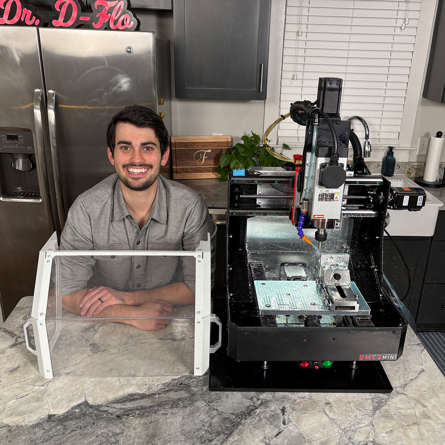
The DMC2 Mini is one of the most capable desktop CNC mills you can buy — if you’re willing to build it. With linear rails on all axes, a 3 HP spindle, automatic probing, and flood coolant, this $2500 kit punches way above its weight. It fits on a 24" workbench, plugs into a standard outlet, and still offers a generous 12″ x 7″ x 5.5″ machining envelope.
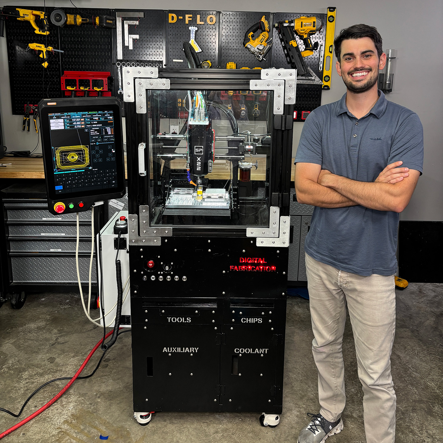
I walk through the base machine in my YouTube video: The Best Benchtop Mill… If You Can Build It! (DMC2 Mini). But that’s just the beginning. There’s a lot of room to upgrade, including the control system, enclosure design, and spindle. This page documents every major improvement I made as part of my follow-up video: Building the Ultimate Compact CNC Mill — Not Just an Upgrade!
Each section below includes CAD files, parts lists, and tips to help you recreate (or improve on) what I built. While focused on the DMC2 Mini, many of the upgrades and instructions are broadly applicable. If you’re retrofitting a MASSO controller onto an older machine or stepping up to a Spinogy spindle, you’ll find useful wiring guides here.
Disclaimer: This project was created in collaboration with Masso, Spinogy, Shariff DMC, and OSH Cut who provided components featured in the build. I am not affiliated with any of these companies beyond this collaboration. If you need technical support or replacement parts for the base DMC2 Mini kit, please contact Shariff DMC directly. Affiliate links are present below.
License: This project is licensed under BY-NC-SA 4.0. Users are allowed to adapt and remix the work but all contributions must be distributed under the same license as the original (e.g., noncommerical). The base 3D model cannot be redistributed, but modifications that unlock new features or significantly improve the base function of the printer can be shared. For any questions on this license please contact Dr. D-Flo.
Electronics Enclosure Upgrade
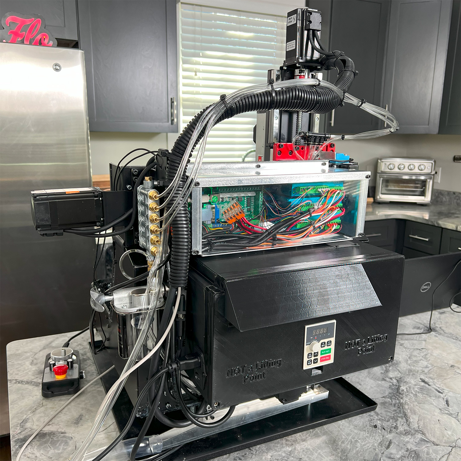
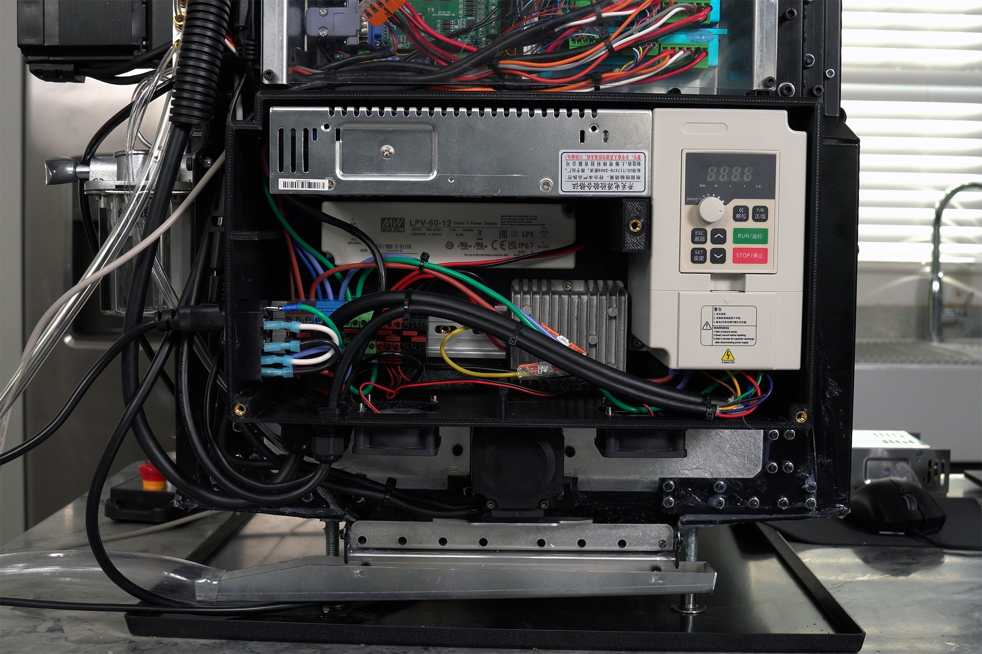
The stock DMC2 Mini ships with a mess of external power supplies. You’re stuck plugging in four cords just to run the machine. That includes two separate 12V supplies (one just for the coolant pump to avoid interference), a 36V supply for the motors, and the VFD.
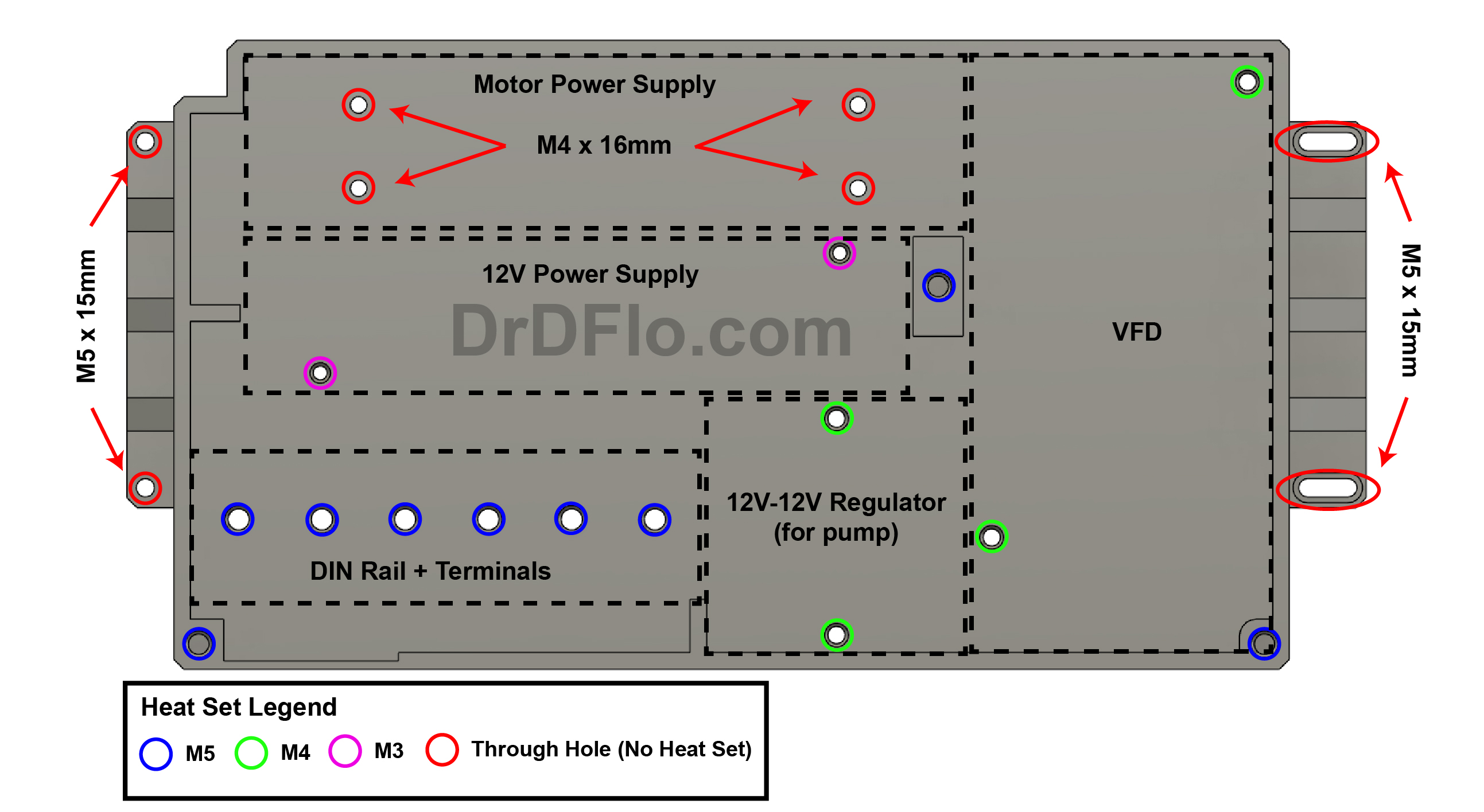
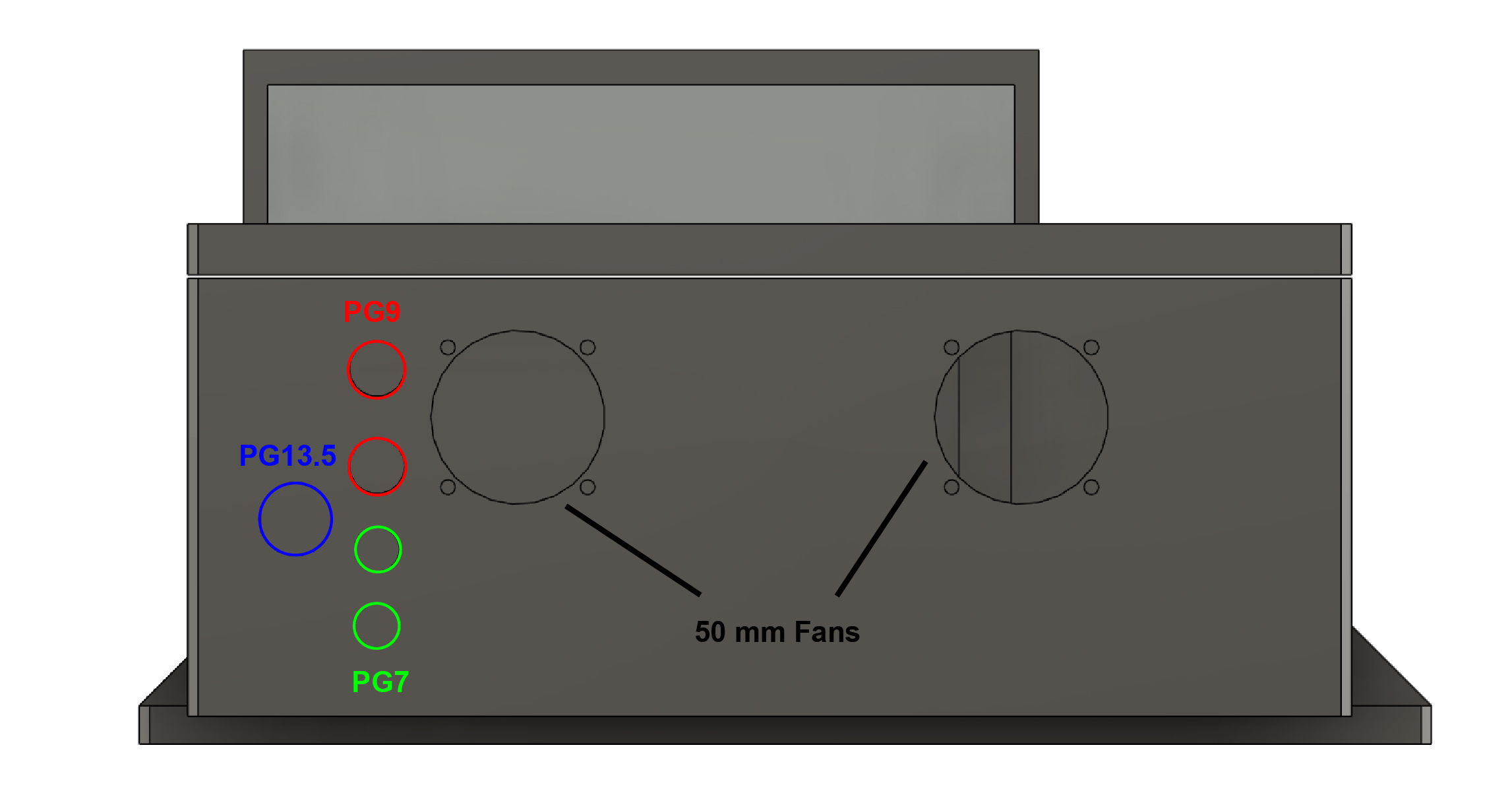
This upgrade consolidates everything into a single printable electronics box mounted directly to the machine. Watch it come together here.
Your 3D printer must have a build volume of 335 mm x 189 mm x 134 mm for this model. It is recommended to print the model out of PETG, preferably reinforced PETG to prevent warping. PLA does not have sufficient heat resistance.
I sell assembled units. Reach out if interested: [email protected]
X-Axis Motor Upgrade
The stock X-axis motor mount that ships with the DMC2 Mini is a 3 mm (11 ga) bent steel bracket. Unfortunately, the mounting holes are located on the opposite flange from the motor, which creates a long lever arm that leads to noticeable flex and wobble.
In the first DMC2 Mini video (52:46), I designed and machined a thick mount (8 mm) out of aluminum. This two-part assembly ia a great starter project for milling your own parts, and I’ve included the CAD files for it below.
But if you'd prefer an off-the-shelf solution, the HM10-57 mount, which I used in the second video (17:49), is a rigid NEMA 23 bracket compatible with the DMC2 Mini. The HM10-57 is not compatible with the small sheet metal component for the enclosure.
Y-Axis Way Cover
The DMC2 Mini ships with individual dust covers for the HGR15 rails. While these do keep the coolant and debris out, they also cost you about 25 mm of Y-axis travel on the front end due to how they compress when mounted.
To solve this, I replaced the front two dust covers with a single continuous flat bellow from McMaster-Carr (Part #: 1320K111). I 3D printed two mounts: one attaches the bellows to the bed, and the other offsets the mount at the end of the rails—recovering the lost travel. Files are below. Ultimately, this modification will be important for my tool changer setup. You can watch the install in part 2 (32:57).
A few things to keep in mind:
- This upgrade is not compatible with the stock enclosure.
- Chips can still collect in the bellows’ folds, so you’ll want to brush them out occasionally.
- You’ll need to drill mounting holes in the base plate of the DMC2 Mini to install the end bracket.
- The homing sensor may need adjustment. If your inductive sensor or the trigger flag is positioned for the stock rail ends, you may need to reposition them to accommodate the new travel range. The below model includes a new mount of flag for installing a MASSO optical switch.
It may take a minute for the embedded model to load.
If the 3D viewer is not working above, then you can download the .f3d, .STEP, or .ZIP folder with 3MFs.
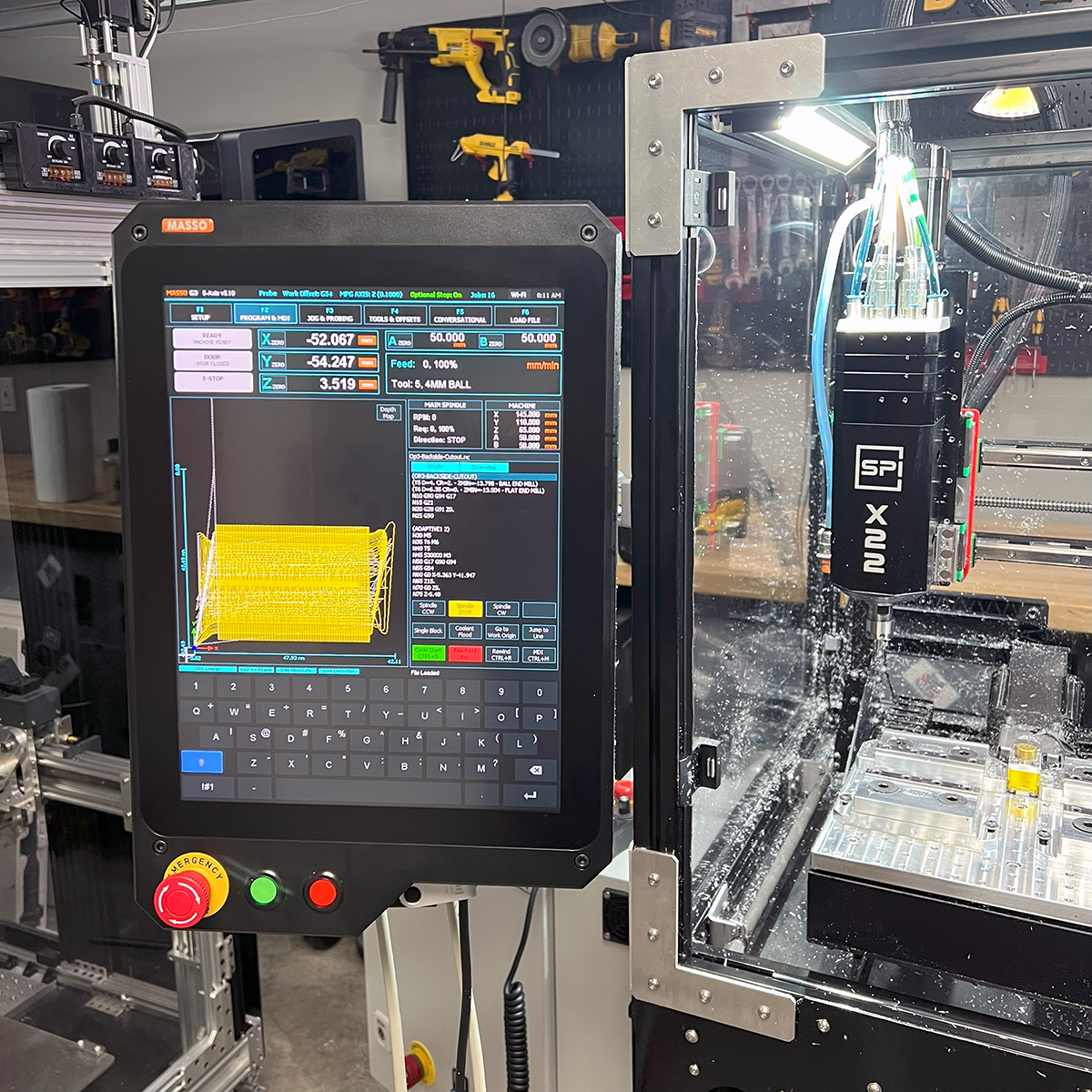
MASSO Controller
The MASSO G3 Touch is a great option if you want a powerful, all-in-one CNC controller that just works. It was by far the easiest board I’ve ever programmed. No digging through config files, just a clean settings menu where you assign functions to pins and instantly see their state. If this is your first CNC build or conversion, MASSO will save you an enormous amount of time and frustration compared to open-source solutions (e.g, LinuxCNC) or complex industrial controllers.
While the MASSO G3 Touch makes CNC control feel refreshingly simple, there are a few important limitations to know about, especially when it comes to wiring and customizability. Most users will run into at least one of these during their build, so it’s worth reviewing them early.
1. Inputs require external pull-up resistors
The MASSO’s digital inputs don’t have internal pull-ups, which means you’ll need to add resistors manually for reliable switching behavior on components like limit switches, push buttons, motor alarm signals, and probe inputs. These external resistors add complexity to the wiring and must be insulated with heat shrink to prevent shorting out the board.
Solution:
MASSO sells an extension board that includes configurable pull-up resistors via dip switches.
2. Outputs are limited to 5 mA
That’s not enough current to directly drive most relays, which are commonly used to control solenoids, coolant pumps, and other CNC peripherals.
Solution:
You’ll need a relay module with built-in signal amplification. I recommend this
two-channel relay module,
which uses Darlington transistors to boost the weak output signal.
MASSO also offers a dedicated relay module designed to work with their controller — either option will work.
3. Narrow E-stop voltage window
The emergency stop circuit holds at around 2.3 V during normal operation and drops to 0 V in a fault.That small voltage difference can be difficult for some safety circuits or external logic devices to interpret reliably.
Solution:
MASSO’s relay module is again the easiest fix here, as it's designed to respond to these small voltage swings. If you're designing your own interface, you’ll need to make sure it reliably detects 2.3 V as a logic high. Keep in mind that only up to two low-current relay inputs can be connected to the E-stop output due to its limited current capacity. For more details, refer to the MASSO Documentation.
4. Low maximum step rate (100,000 steps per second)
MASSO’s step rate limit introduces a tradeoff: if you want smoother motion (via smaller step sizes or microstepping), you may have to reduce speed. Conversely, to hit higher speeds, you’ll need coarser steps, which can make motion rougher.
Solution:
This isn’t a dealbreaker for most hobby or prosumer machines, but it’s something to be aware of.
If you're planning on very high-speed machining or fast travels, you may need to carefully tune your steps-per-mm and microstepping settings or consider a controller with a higher step rate if it's critical for your application.
5. No user-defined macros (as of V5.1)
All common operations like probing and tool changes follow fixed, pre-programmed routines that can’t be modified or re-ordered.
For example, the probing cycle only works in one direction if you're using an off-axis probe (directional offsets not possible). The probing issue is described further in the video (32:24). And the tool change process supports only a limited number of configurations and must follow MASSO’s hardcoded sequence.
Solution:
If you need full control over motion sequences or want to integrate custom hardware, you'll likely run into walls with MASSO’s closed system. For most users, the built-in logic is fine but advanced workflows may require a more flexible controller.
Map it out!
Take the time to plan your wiring using these .AI (Adobe Illustrator) or .SVG (generic vector artwork) templates. A clear diagram will save you hours during assembly and troubleshooting.
Warning: Always double-check your wiring against the diagrams before applying power. Incorrect wiring can damage components. If you spot an error in the wiring diagrams, please report it to Dr. D-Flo.
Stepper Motor or Drive Wiring
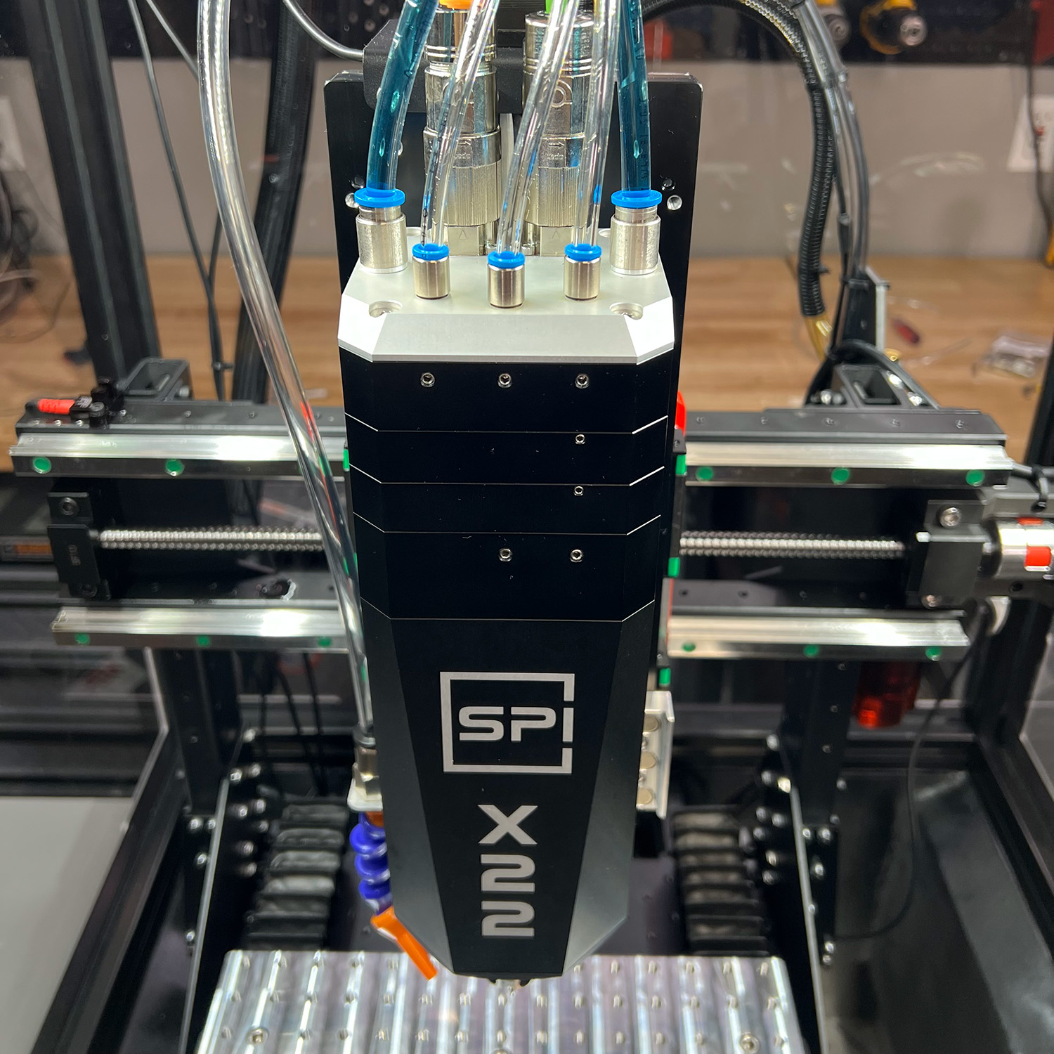
The motor shown below has an integrated stepper driver, which simplifies wiring. If your motor does not include a built-in driver, you'll make these same connections — power, step/dir signal, alarm, and enable — directly to the external driver instead.

Stepper motor wiring .AI (Adobe Illustrator) template. Right click and save on the image above to save .SVG.
MASSO G3 Touch + Stock DMC2-Mini

Stepper motor wiring .AI (Adobe Illustrator) template. Right click and save on the image above to save .SVG.
MASSO G3 Touch + Spinogy

Stepper motor wiring .AI (Adobe Illustrator) template. Right click and save on the image above to save .SVG.
Work in progress coming soon
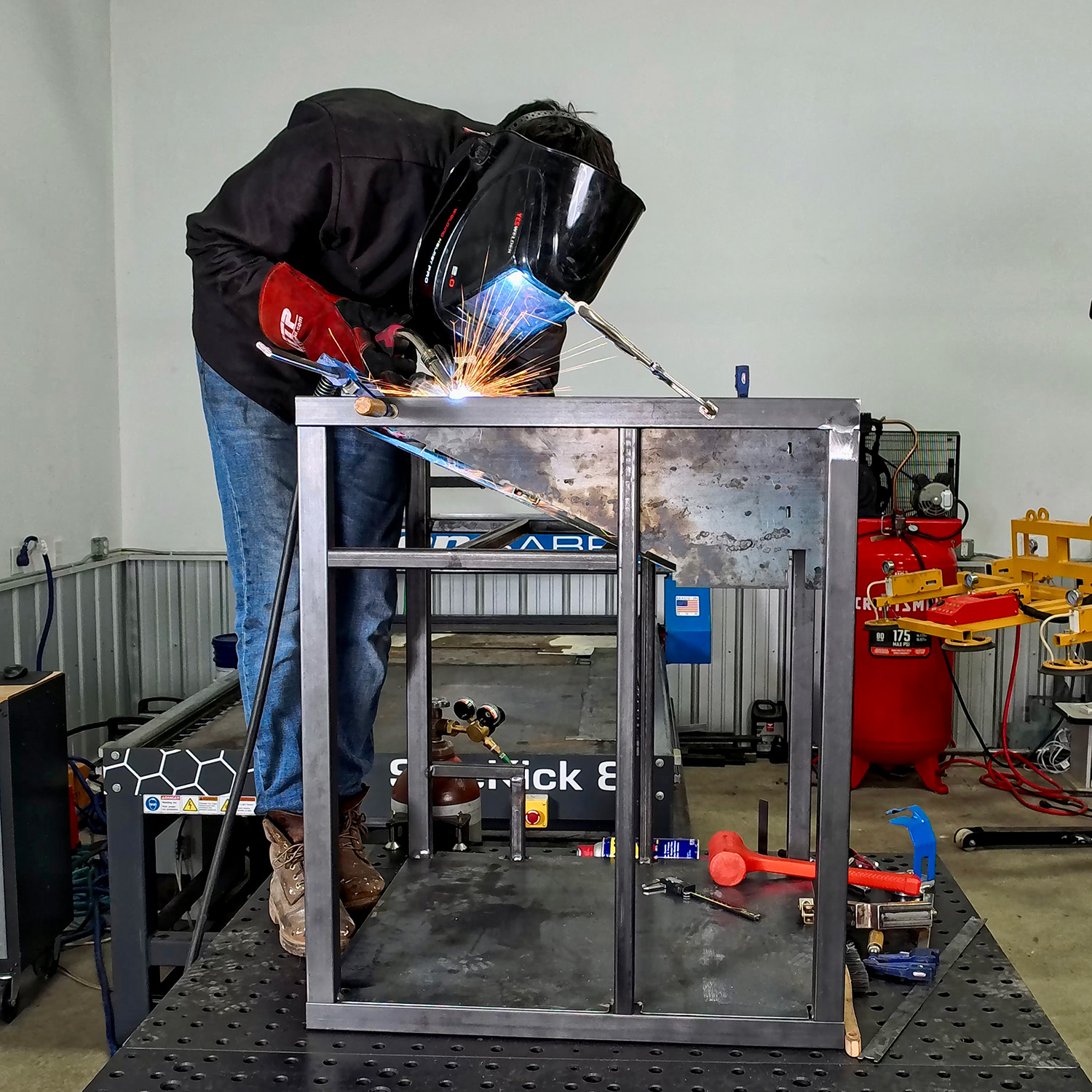
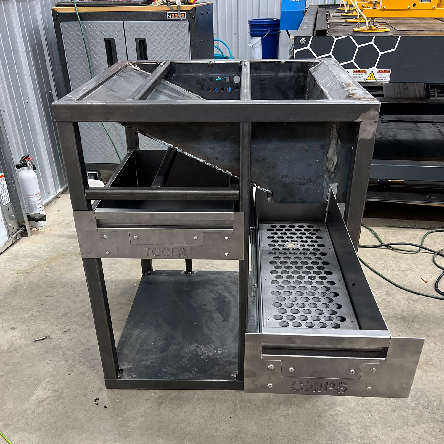
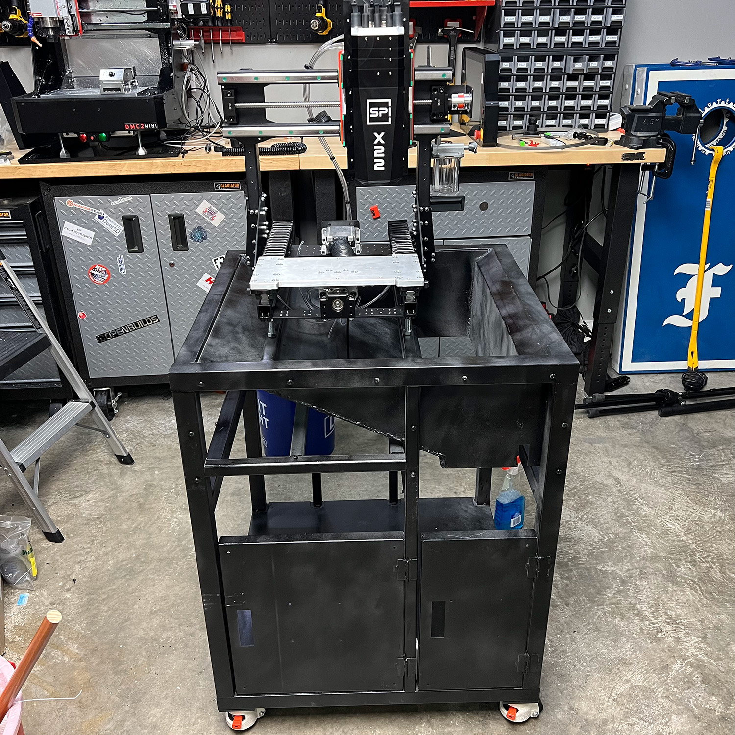
Stand and Enclosure
Open-Source Content
Dr. D-Flo’s #1 priority is ensuring uninterrupted access to his digital fabrication content for everyone. Information and project files are free without any intrusive advertisements. The goal of this website and YouTube channel is to inspire more makers, DIYers, machinists, fabricators, and engineers as we need physical solutions for many of the problems facing our society.
If you find yourself in a position to contribute, we would greatly appreciate your support through becoming a YouTube channel member, a one-time donation, or purchasing your tools through Dr. D-Flo’s Amazon store.
Discussion and Feedback
Do you need more help? The best way to get your questions answered by Dr. D-Flo and other DIYers is to post a question on the forum. Click here for the forum topic specific to this project.
Rate this Project: or
Did you encounter broken links or misinformation while reading this article? Please bring these issues to our attention by providing your feedback below. This forum and email should not used for technical help. All help requests should be posted on the forum.