Cost:
$1000
Time:
24 Hours
Skill:
Expert
Project Overview
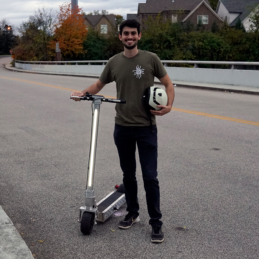
Up until recently I rode a Gotrax E-Scooter to work every day. The scooter retailed for $300, but the value was incredible. I did not have to pay for gas to get to work or a parking spot that costs an arm and a leg. However, after about a year and a half of driving the scooter daily the battery started to lose charge quickly and there were a couple other mechanical issues that forced me to stop riding the scooter. Instead of purchasing a new scooter, I decided to go the DIY route as an excuse to use all my newly minted CNC machines to build a one-off scooter that fits my needs.
Before I get into the design criteria of the scooter, I want to point out that this project page is going to serve more as a repository for scooter building versus a step-by-step guide for how to build this scooter (i.e. the cyber scooter). It’s unlikely that very many people will attempt to build this exact scooter due to the need for sophisticated machinery not found in the average garage. However, through building this scooter and the YouTube comments on the accompanying video I have learned a lot about electric hub motors and their controllers, LiPo batteries, braking systems, and generally how to fabricate parts. You may find this information useful when working on projects that use similar components.
Resources
The BOM may contain affiliate links that provide monetary kickbacks to Dr. D-Flo. These funds are used to pay for this website and future projects.
As mentioned in the introduction, this project requires machinery not found in the average garage, namely, the CNC mill and plasma cutter. If you have the money, then you can supply the files in the downloadable section to a machine shop and they can make you the parts. However, this method will be extremely cost prohibitive and it may be better to use this project as an excuse to build your own CNC mill.
Affiliate links may be present.
- A little self-promotion here, but if you are new to CNC motion, then checkout my written guide and video on how to build a 3D printer. Many of the concepts that go into building a 3D printer translate over to a CNC plasma cutter build.
- OpenBuild's documentation provides troubleshooting to common problems, like incorrect stepper motor wiring and electromagnetic interference (EMI).
- Miller's How To Select And Operate A Hand-Held Plasma Cutter is great for resource for those who are new to Plasma cutting.
Walk Through
1. Selecting Compatible Electronics
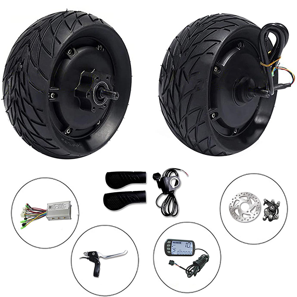
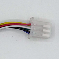
Figure 1. Electric scooter components purchased as a set from Amazon.
As you could probably tell from the BOM, I purchased all the electronics, including the motor, controller, throttle, brakes and LCD as a set (Figure 1). I did this because it was impossible for me to decipher at the time which motor controller and motor would be compatible with each other. I noticed that there was a variation in not only the size of wheels that contained the hub motor (8”, 10”, etc.), but also that there were internal differences within the motor, such as a varying number of magnetic poles. Without any supporting documentation, it was impossible to conclude which motor worked with which controller, so I purchased a set.
What I discovered later was that while there seems to be an infinite number of brands selling scooter electronics, most of these resellers are using the same OEM parts, which are all compatible with each other or are wired in such a way to accept multiple types of components or motors. For example, the motor controller that I used could be programmed to work with motors that had a different number of magnetic poles. Further, the diameter of the hub motor could also be entered into the controller so that the speedometer on the LCD reported the correct speed.
2. Voltage and Wattage
There are two parameters that you do need to be careful to match if you decide to source components individually: voltage and wattage. Motors can typically operate at different voltages, with higher voltages being preferable for increased motor performance (i.e., speed). However, the controller can only operate at one voltage. If you supply too high of a voltage then you will fry the controller and too low of a low of a voltage the controller will fail to turn on. Motor controllers come in 24V, 36V, 48V, 60V, and 72V variants with the first three voltages being the most popular. As mentioned previously, higher voltages are preferable but it can be difficult to find a battery that supplies 60 or 72V that is small enough for scooter use. For the Cyber Scooter I used a 48V controller and 48V battery.
Wattage (W), the second parameter, also needs to be considered carefully. Wattage is a unit of power and is equal to the current multiplied by the voltage (Amps x Volts). It’s important to match the wattage of the motor, which is its peak power draw, with the wattage that the controller can handle. A 1000W motor should be paired with a motor controller that is rated at least for 1000W. A mismatched rating between the controller and the motor can result in too much current flowing through the controller, which can result in excessive heat and damaged components.
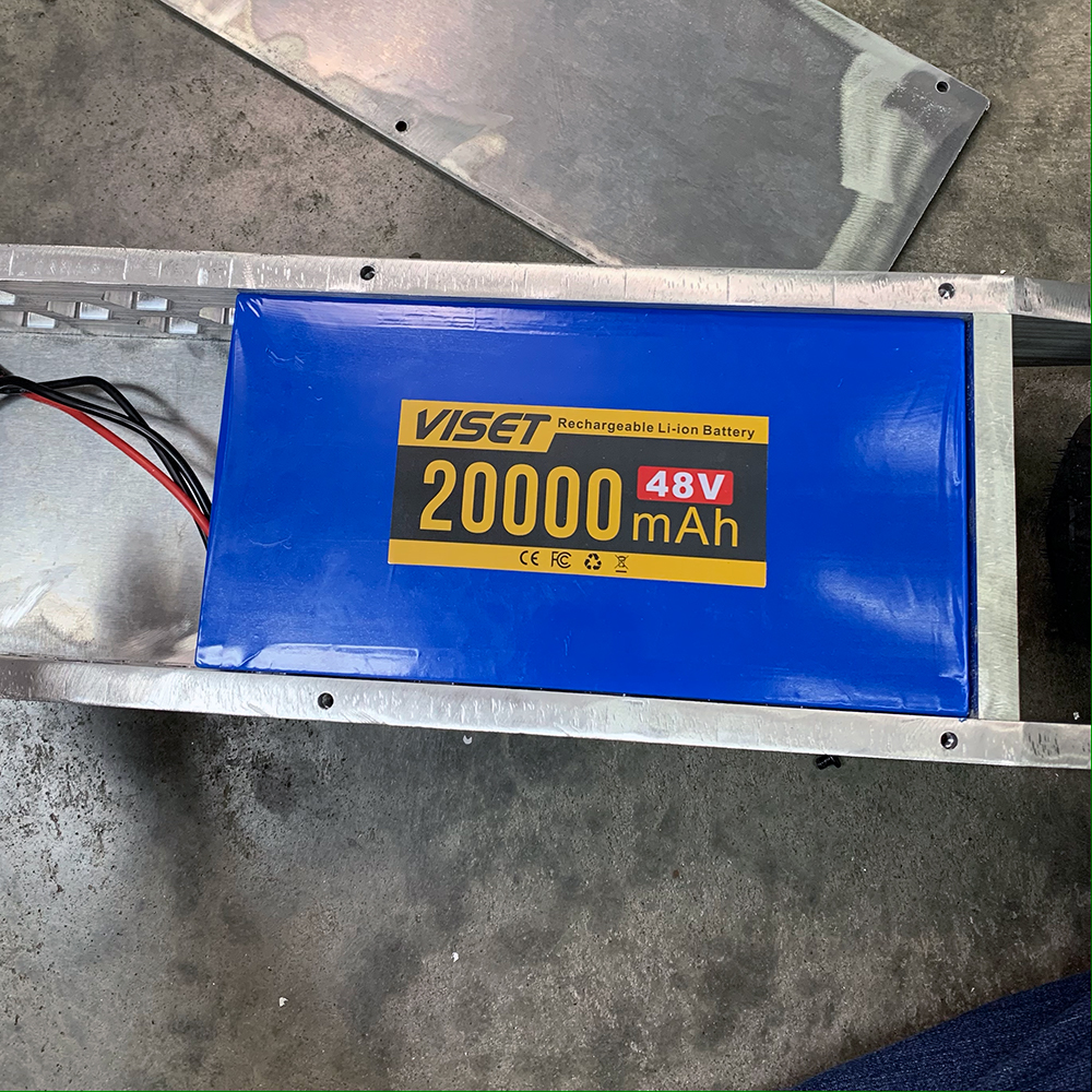
3. Sizing the Battery
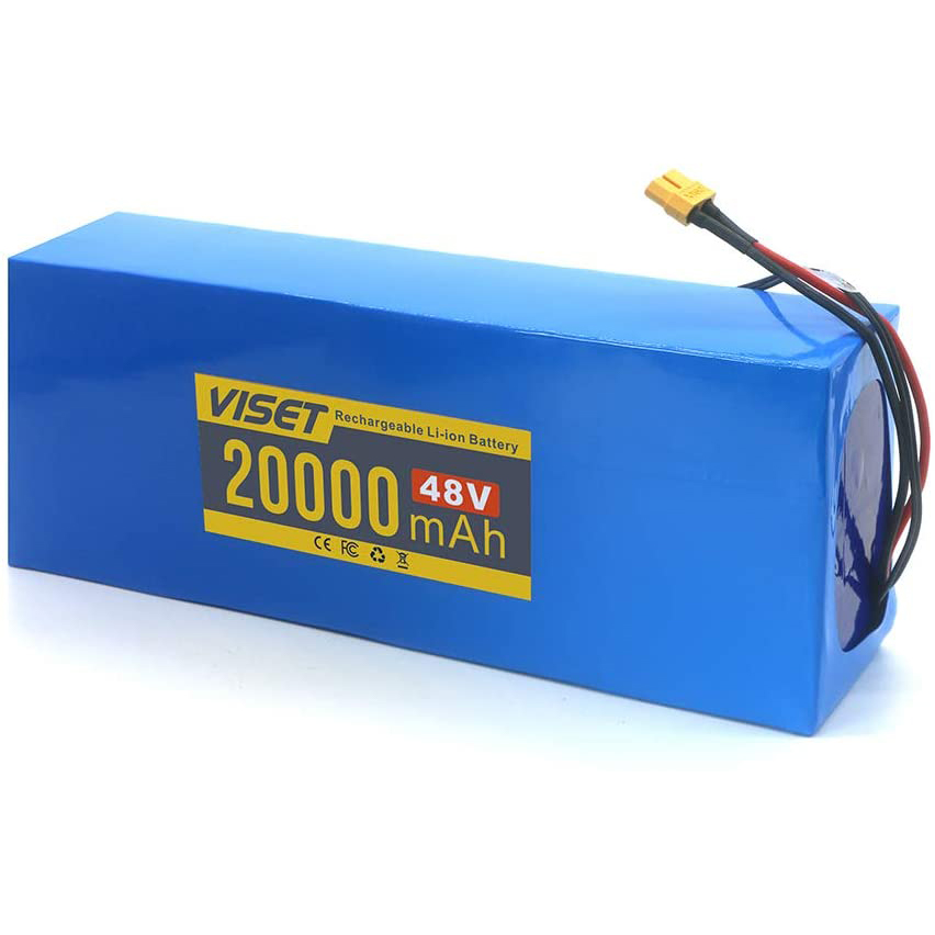
Figure 2. A 48V, 20Ah (960Wh) battery allows for 1 1/2 hours of ride time on the Cyber Scooter. The battery was sourced from Amazon.
The battery is the source of power and it needs to be able to supply the required voltage with enough current to meet the power draw (wattage) of the motor. Battery specifications include the voltage and Amp-hours (Ah), with the ladder being a measurement of the capacity of the battery. A battery with a 1 Ah rating can supply 1 amp of current at the battery’s voltage for 1 hour before the battery becomes fully discharge. This same battery could supply 2 amps for 30 minutes, 4 amps for 15 minutes, and so on (kind of). If you draw too much current from a battery then two things could happen 1) the battery overheats leading to battery damage or 2) the voltage will drop due to internal resistance of the battery. Recall that too low of a voltage will lead to the motor controller turning off. Therefore, it is important to size the battery correctly so that your E-scooter has enough range and so that the battery functions safely.
It’s easier to pick the correct size battery based off watt-hours (Wh). Similar to Ah, Wh describes how much watts the battery can supply for an hour, but this unit takes into consideration the voltage of the battery. Personally, I try and match the watts of the motor to the watt-hours of the battery, so that I know I will be able to ride my scooter for at least an hour before having to charge it. The battery listed in the BOM for the Cyber Scooter is 960Wh (48V * 20Ah). A motor will not continuously draw its full wattage in an E-scooter application because most likely your commute will not be entirely uphill. In hilly Tennessee I can ride my scooter for about an hour and a half before needing a recharge. The only downside to using a large 1000Wh battery is cost and weight. If you want your E-scooter to be lighter and more maneuverable, it might be worth considering a 500Wh battery. However, I would not use a battery with a Wh less than a quarter of the maximum current draw of the battery for the aforementioned high current draw concerns and low scooter range.
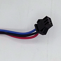
4. Wiring the DC Motor Controller
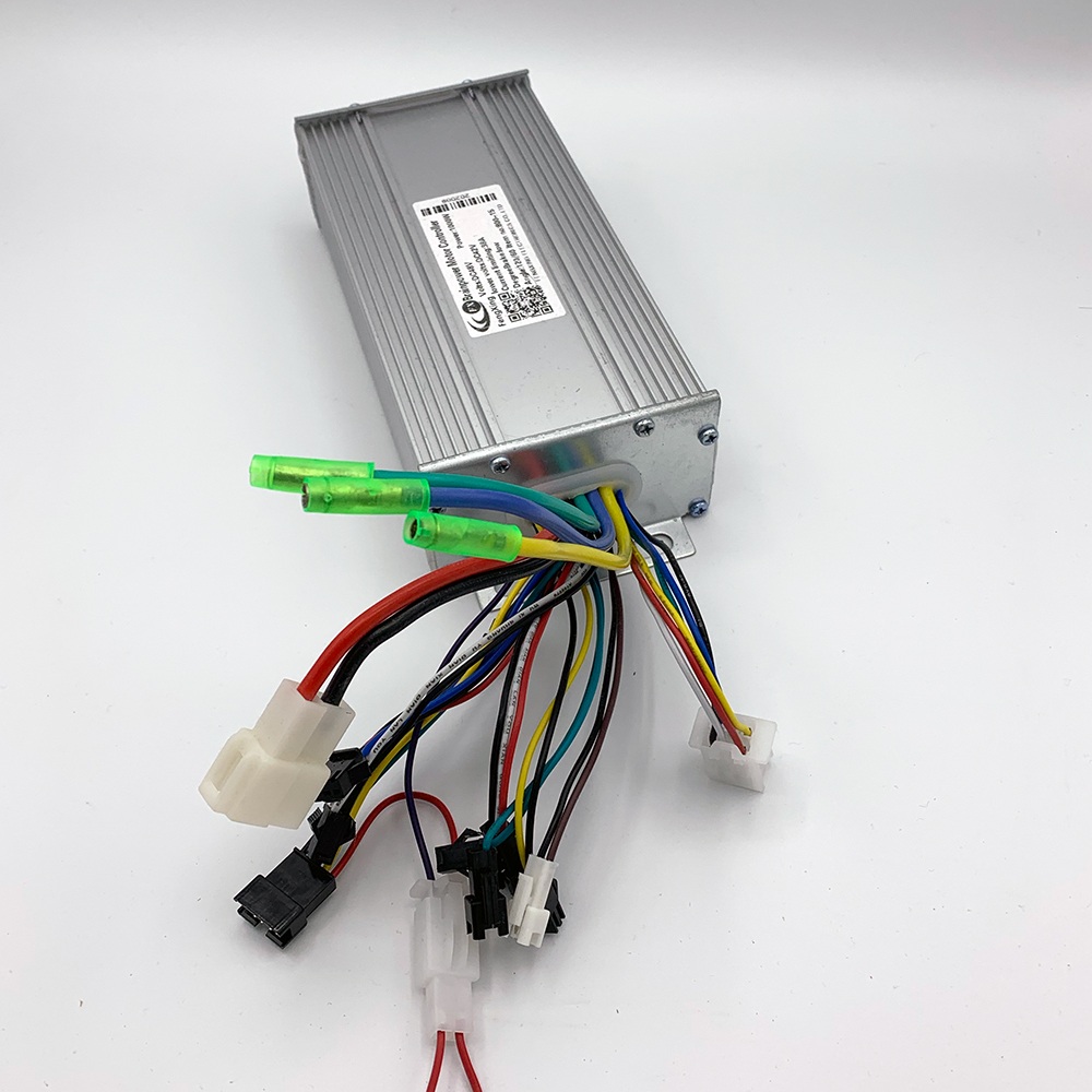
Figure 3. 1000W DC motor controller for E- Scooters and bikes.
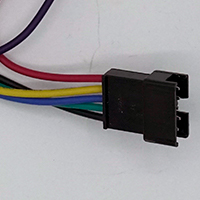
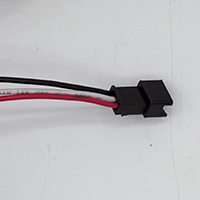
When you purchase imported products you always run the risk of receiving an item with little to no documentation. This was exactly the case for my e-scooter kit that I ordered from Amazon. I did not receive a single piece of paper. The only documentation I had were two blurry images on the Amazon listing. The first image was a picture of the motor controller where the wires that were coming out the box were labeled generic names. The purpose of most of the wires were self-explanatory, but some wires had strange names, such as self-learning, assistant, and cruise. The table below contains a brief explanation of the purpose of all the wires coming out of the motor controller. These functions will be relatively consistent across most motor controllers. Note that not all wires are required for an E-scooter to function and the wire colors listed below may vary from controller to controller but red wires should always be positive voltage, black wires negative voltage, and all other wires will most likely be signal wires. Be careful not to mix up signal and power wires because they may be at different voltages.
DC Motor Controller Wiring Table
| Name | Number of Wires | Function | Required? | |
|---|---|---|---|---|
|
Power Supply | 2 (Red, Black) | Power inputs from battery. | Yes |
|
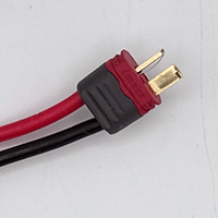
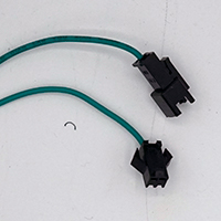
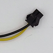
Motor phase wires | 3 (Yellow, Blue, Green) | Supplies power to the Motor | Yes |
|
Hall Sensors | 6 (Red, Yellow, Black, White, Blue, Green) | Power, ground, and the signal wires from the 3 (possibly 4) Hall sensors. | Yes |
|
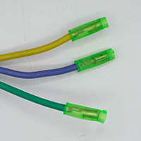
LCD Display | 5 (red, Yellow, Blue, Green, Black) | Connecting point for an LCD display. | Yes |
|
Throttle | 3 Wires (Red, Black, White) | Power, GND, Signal for increasing the speed of the motor. | Yes |
|
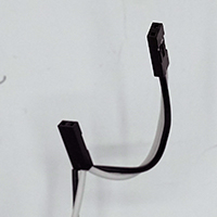
Brake | 2 Wires (White, Black) | Cuts power to the motors when brake levers are triggered. | Yes |
|
Self-Learning / Smart Wires | 2 Wires (Green/White) | These two wires can be used to condition the controller to power the motor without Hall sensors (not recommended). | No |
|
Assistant | 3 Wires (Red, Black, Blue) | E-bike function for pedal assistance. | No – E-Bike only feature. |
|
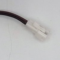
Reverse | 2 Wires (Brown, Black) | Reverses the direction of the motor when the throttle is pulled. | No – direction of motor can be swapped by switching two of the three phase wires. |
|
Cruise | 2 Wires (Brown, Yellow) | Connecting the cruise wires to a switch will cycle on/off the cruise function, which is used to maintain a constant speed. | No |
This is not an exhaustive list by any means. Higher end motor controllers will have wires for regenerative braking, more extensive anti-theft countermeasures, and other more sophisticated features. From my research it does appear that these motor controllers will work with most hub motors and scooter accessories. However, it is best to confirm that the LCD will support the added features.
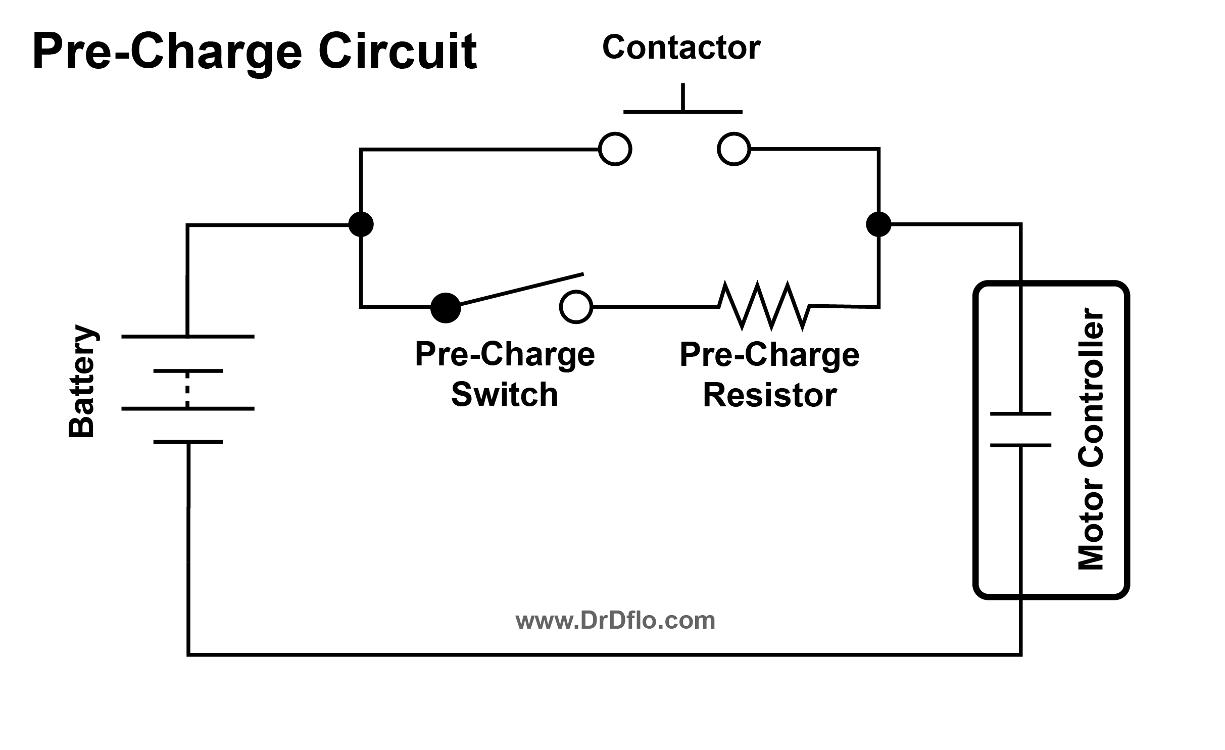
5. Pre-Charge Circuit
The motor controller has a high capacitive load and when the battery is connected, a large amount of current will rush into the controller. Not only does this put a considerable amount of stress on the electrical components in the controller but it can also result in electrical arcing when you connect the wires from the battery to the controller. This bright flash of light can be startling and the surge of current can damage the controller’s internal components. A pre-charge circuit will limit the current that is allowed to flood into the motor controller during start up.
Figure 4 is a simple pre-charge circuit. In the upper leg, the battery is connected directly to the motor controller through a contactor. It’s a good idea to have a physical disconnect between the battery and the controller because even when the controller is off it will still draw phantom power – eventually draining the battery below the safe limits. In a parallel path, the battery is also connected to the controller through a switch and resistor, which make up the pre-charge components. With the battery applying a fixed voltage, the resistor will limit the current flowing into the motor controller during startup. The order of operations for turning on a E-scooter with this pre-charge circuit is important. First, the pre-charge switch is turned on for a couple of seconds, then the contactor is flipped on for the main power supply, and finally, the pre-charge switch is turned off. The exact value of the pre-charge resistor will depend on the capacitance of the motor controller based on the following equation:
R = T / (5C), where R = Pre-Charge Resistor (Ohms), T = Pre-Charge Time (Seconds), C = Capacitance (Farads)
The pre-charge time (T) needs to be about 0.5 seconds because too long of a startup can confuse the logic in some motor controllers. The capacitance (C) can range from 0.01F (Farad) to as much as 1F depending on the type of motor controller. We will assume 0.01F of capacitance because smaller motor controllers used in E-scooters have less capacitance. A more precise capacitance value can be obtained by opening the motor controller and adding together the capacitors, but this could disrupt the moisture seals. Calculating the resistance value from the formula below yields a 10 Ohm resistor. It is definitely interesting that time divided by capacitance is equal to resistance. If you found this little fact interesting like I did, then you can see the derivation here. The higher the wattage resistor the safer. I recommend at least a 10W resistor for use in a pre-charge circuit, like the one I used in the Cyber Scooter build.
Perhaps, you don’t like the idea of having multiple switches to turn on your E-scooter. Automatic pre-chargers exist, where they will switch between the pre-charge circuit and the normal power circuit. I was close to purchasing the Zeva Smart Pre-Charger, but the price tag of $50 was a little difficult to swallow when a switch and a resistor can be had for a couple of dollars.
6. Mechanical Design
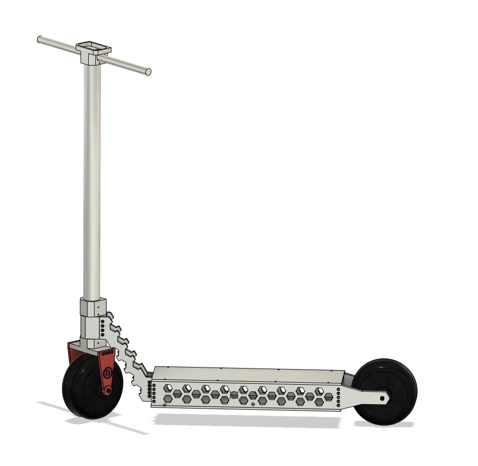
Figure 5. Fusion360 model of the Cyber Scooter. All the STEP files are located in the download section above.
Everyone is probably familiar with how a kick scooter works. The handle bar and the front wheel rotate independently of the deck, which allows the rider to steer. The headset is the bearing assembly that allows the steering column to rotate. The bearings are either tapered roller bearings or sleeved bearings and they are pressed into the head tube, which is connected to deck of the scooter. I cover many of the mechanical aspects of the E-scooter in my video, but I wanted to touch on a couple different design consideration that were glossed over or not implemented.
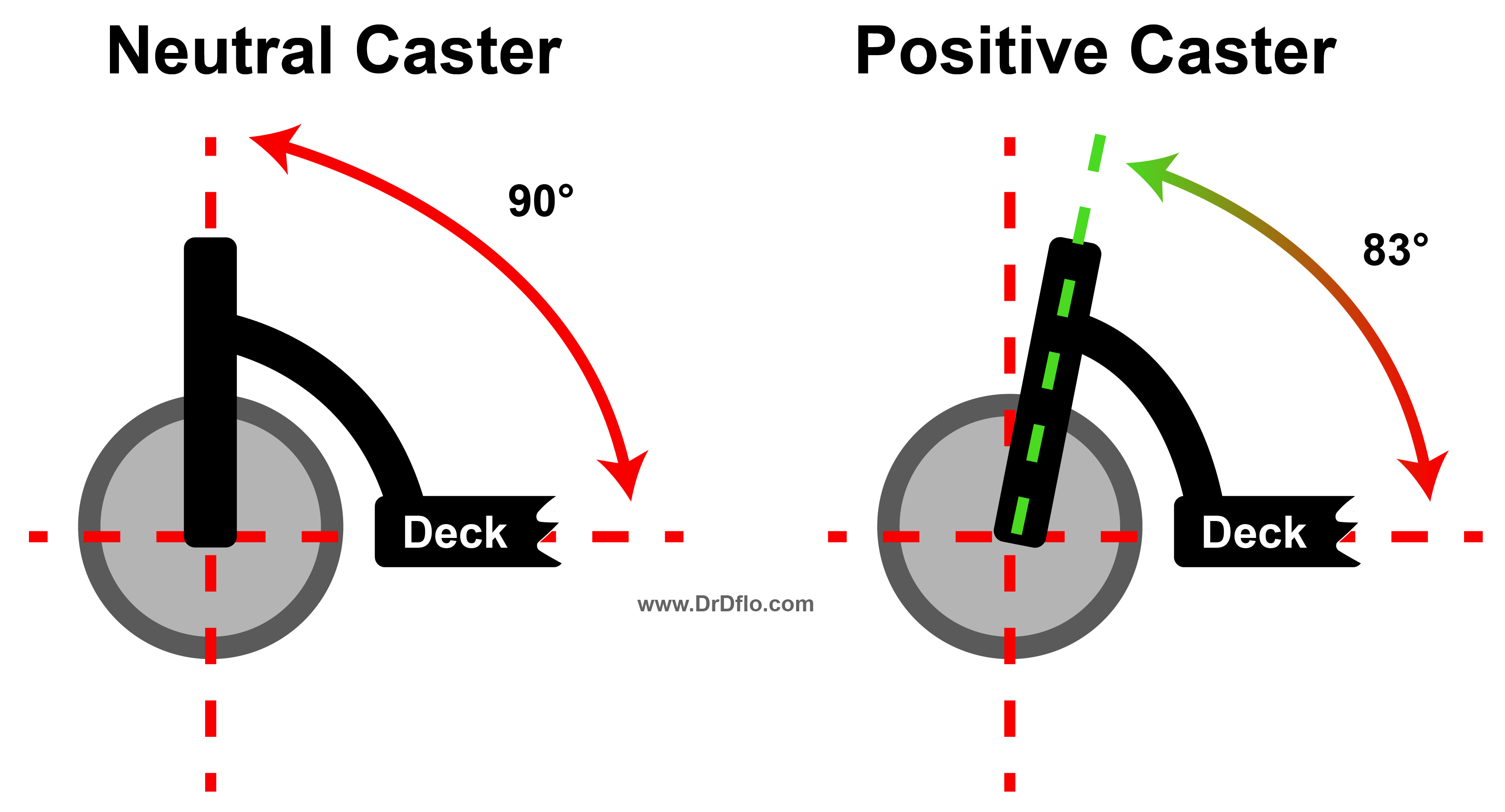
Caster Angle
Caster angle is the angle at which the steering axis meets the wheel. A caster angle of 0° or 90° (depending on whether you are measuring from the vertical or horizontal axis), means that there is no caster (i.e., neutral caster). A positive caster is when the steering column leans towards the rider (Figure 6).
The most obvious benefit of the positive caster is that the handlebars are closer to the rider, making the riding experience more comfortable. What may not be as evident is that a positive caster angle places a force on the front tire that keeps this tire point straight at high speeds. This is very important for the Cyber Scooter, which can achieve speeds of up to 30 MPH. Further a positive caster, also improves handling and cornering performance. For an electric scooter, a caster angle of 83° is optimal.
Discussion and Feedback
Do you need more help? The best way to get your questions answered by Dr. D-Flo and other DIYers is to post a question on the forum. Click here for the forum topic specific to this project.
Rate this Project: or
Did you encounter broken links or misinformation while reading this article? Please bring these issues to our attention by providing your feedback below.