Project Overview
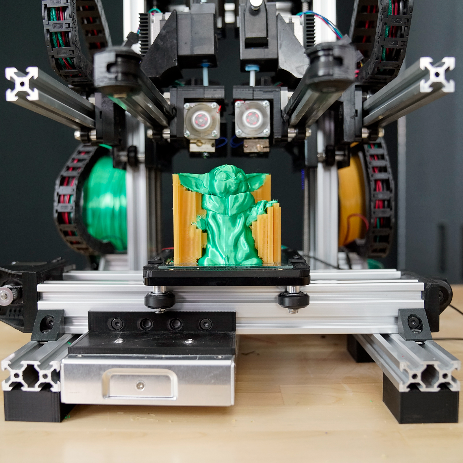
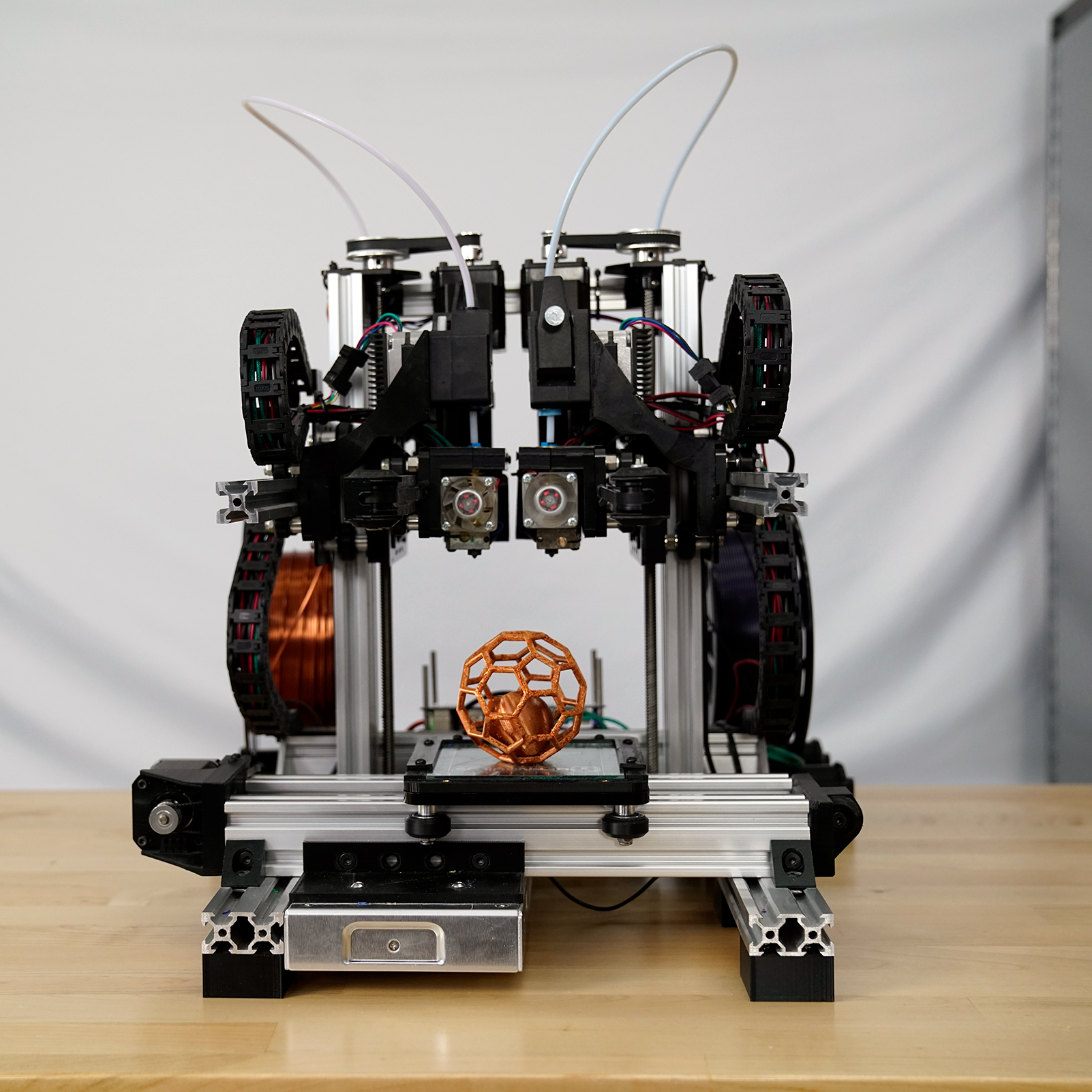
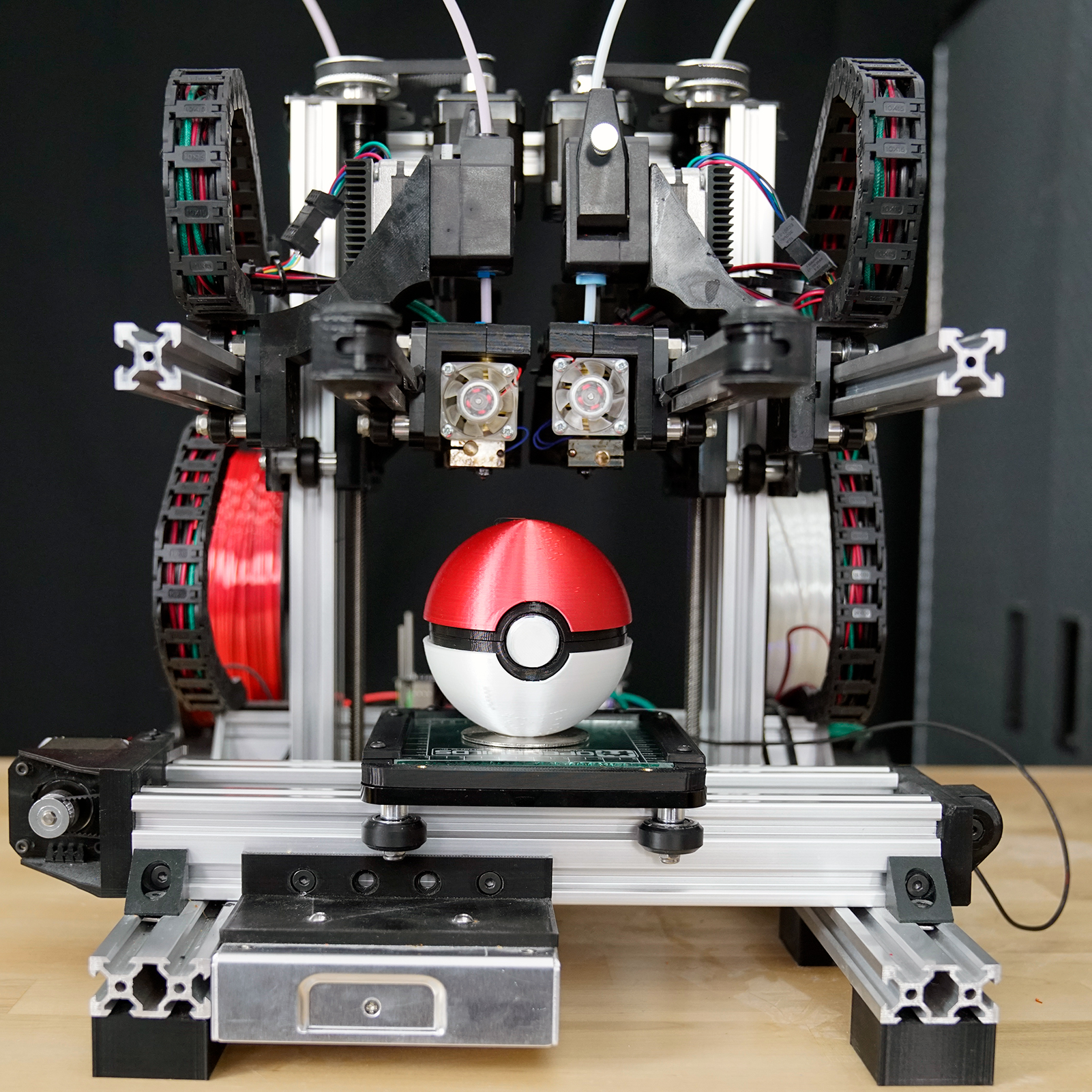
Zidex is a small format 3D printer with two extruders that can be controlled independently in not only the X-axis but also the Z-axis. If you are wondering what the benefits of such a configuration are, then check out my post on Dual Extrusion. The original creator of Zidex is Stephenci and his dedicated Github repository and Onshape model made it possible to build this unique 3D printer. I made quite a few upgrades and changes to Stephenci’s original design, including adding a heated bed and part cooling fans, so if you want to build the Dr. D-Flo version of Zidex download the files below.
Cost:
$1500
Time:
75 Hours
Skill:
Expert
Resources
The BOM may contain affiliate links that provide monetary kickbacks to Dr. D-Flo. These funds are used to pay for this website and future projects.
- A 3D printer (see Recommended 3D printers of 2020 if you need to purchase a 3D printer)
- A soldering iron
- Weller Heat-Set Insert Installation tip
- Allen key or screwdriver set depending on the bolts used
- Engineers Square
- Hacksaw
- Crimping Tool
Affiliate links may be present.
- Read Stephen Cia's OpenBuilds Forum Post about Zidex
- Read Dr. D-Flo's How to Build a 3D Printer
- Learn about RepRapFirmware
Walk Through
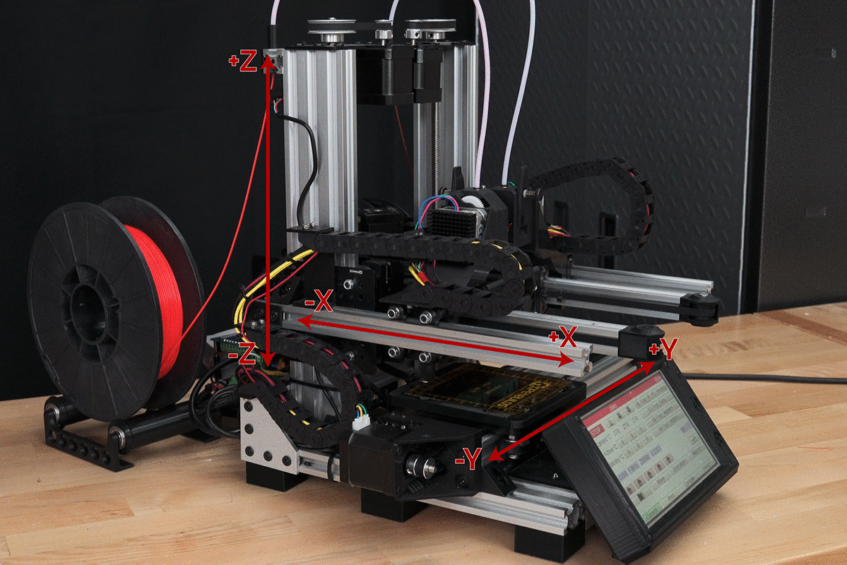
Before we get started with the walkthrough I wanted to provide a fair warning that Zidex is a very difficult printer to build and calibrate. If you have never built a 3D printer before, then I would not start with this printer. Even if you are an experienced DIYer, I still recommend building Zidex with a real life friend or a buddy from the Dr. D-Flo forums. Finally, the biggest drawback of Zidex is its small print bed. However, I would not recommend expanding the print envelope of Zidex because as you increase the length of the cantilevered X-axes it becomes exponentially harder to make them square to the print bed. If you want a printer with a bigger print volume, then it is best to go with a different design.
Step 0: Familiarization
Step 1: Preparation
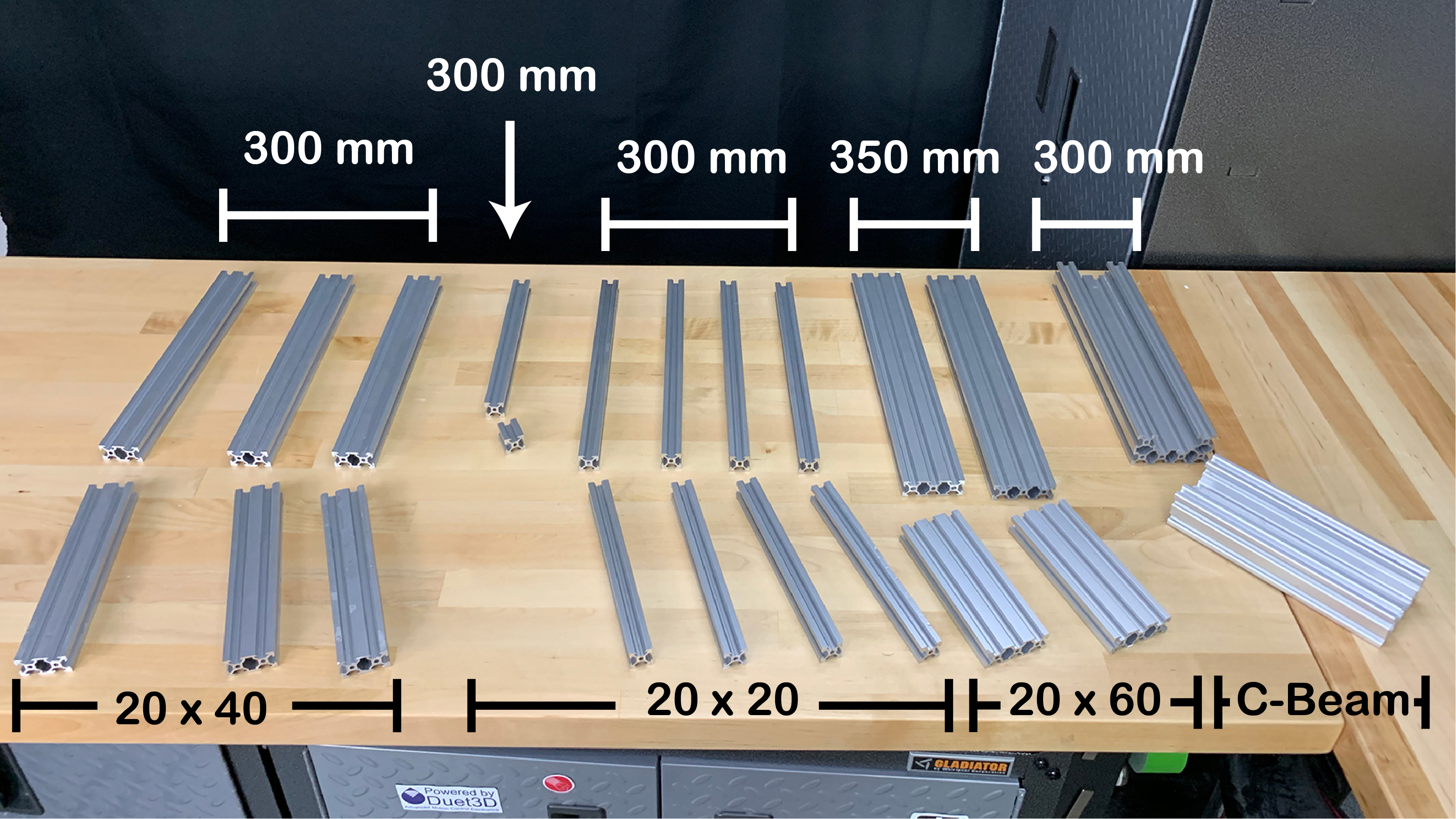
Step 2: The Base
- Both ends of one V-Rail are tapped (M5) in order to attach the L joining plate to the ends with 8mm bolts.
- 8mm M5 bolts and T-nuts are used to attach the L joining plate to the sides of the rail.
- Use an engineer's square to ensure the that the base forms right angles.
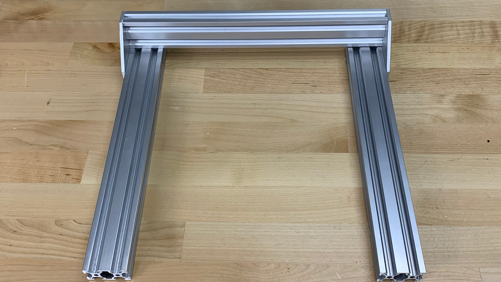
Step 3: Y-Axis
- The Y-Axis Belt Capture (3D printed part) is attached underneath the XL C-Beam Gantry Plate with a 20mm M5 Bolt in the hole shown in Figure 3.
- The GT2 timing belt is wrapped around the Y-Axis Belt Capture prior to sliding the carriage onto the rail.
- 20mm M5 bolts are then used to attach the Y-Axis Idler Capture (3D printed part) and the Y-Axis Motor Holder (3D printed part) to opposite ends of the C-Beam V-rail.
- The idler pulley is then installed into the Y-Axis Idler capture with a 25mm M5 bolt and nut. The belt is then snaked around the idler pulley.
- Four 6mm M3 bolts are used to attach the Nema 17 64 oz.in motor to the Y-Axis Motor Holder. A 20T pulley is attached the motor shaft by tightening the provided set screw. The timing belt is then routed around the 20T pulley.
Step 4: Attaching Y-Axis to Base
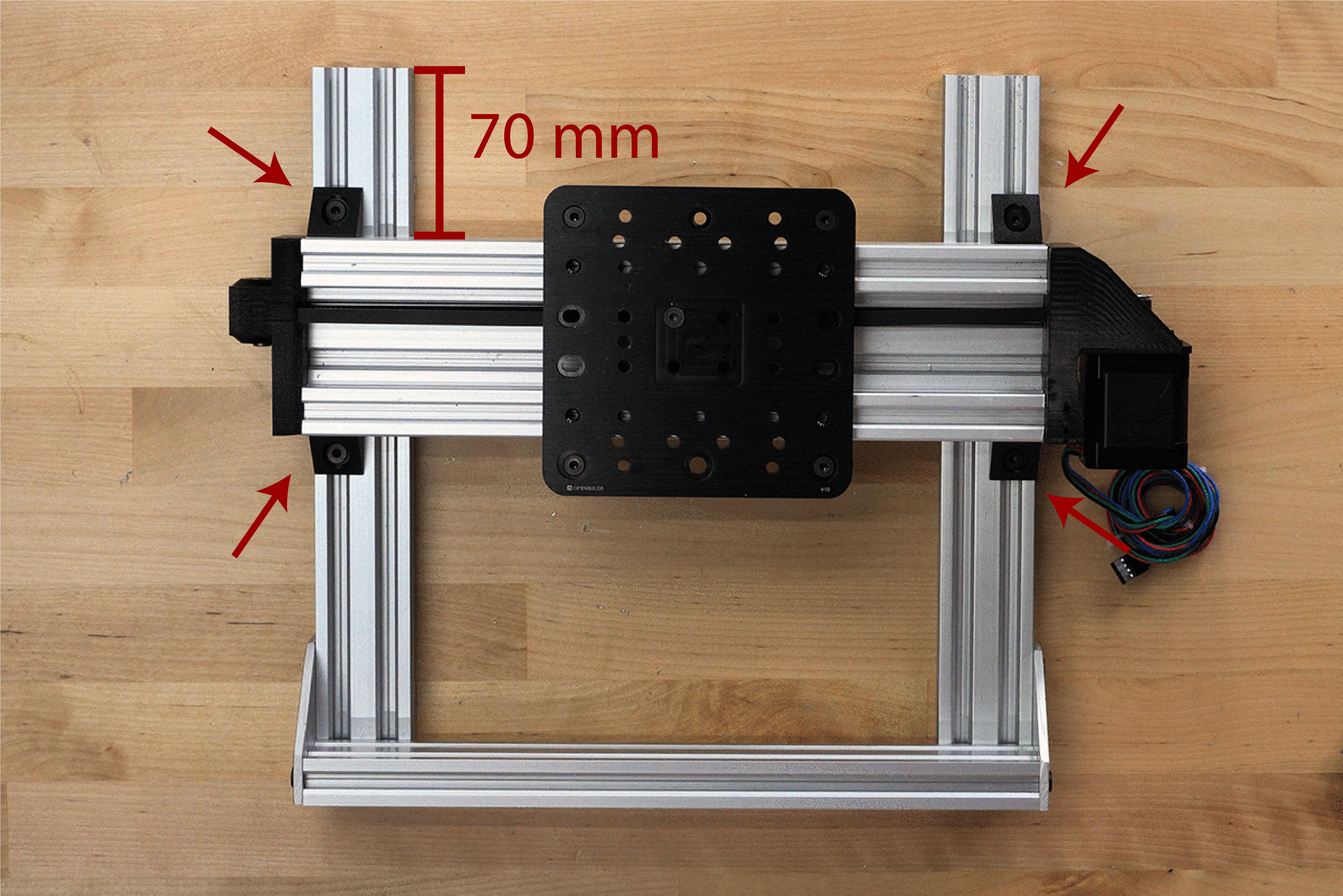
- The Y-axis is attached 70mm from the front of the base with right angled brackets. An engineer's square is used to ensure that the Y-axis is perpendicular to the base.
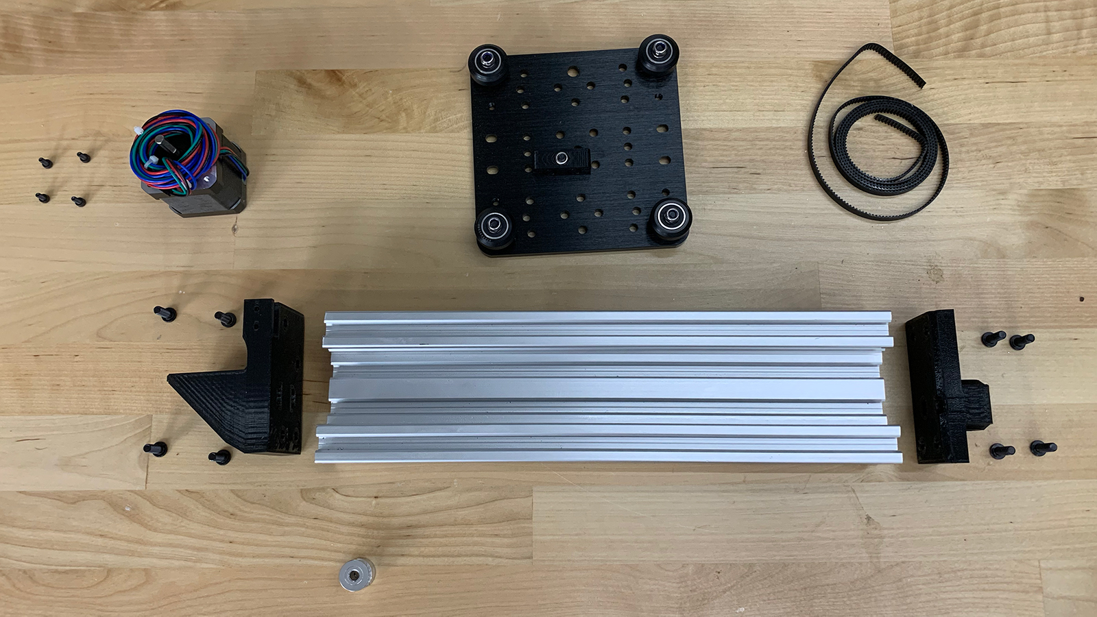
Step 5: X-Axis
- One end of the 300 mm 20x20 V-Rail is tapped for M5 threads.
- The X-Axis Idler Capture (a 3D printed part) is attached with a 5mm M5 bolt to the tapped end of the 20x20 V-Rail. This is not pictured and the How to Build a 3D Printer video should be consulted.
- A 25mm M5 bolt and corresponding nut are used to secure the smooth idler to the X-Axis Idler Capture (a 3D printed part).
- A Mini V Gantry Kit which serves as the carriage for the X-Axis is assembled according to OpenBuild’s instructions and then is slid onto the rail.
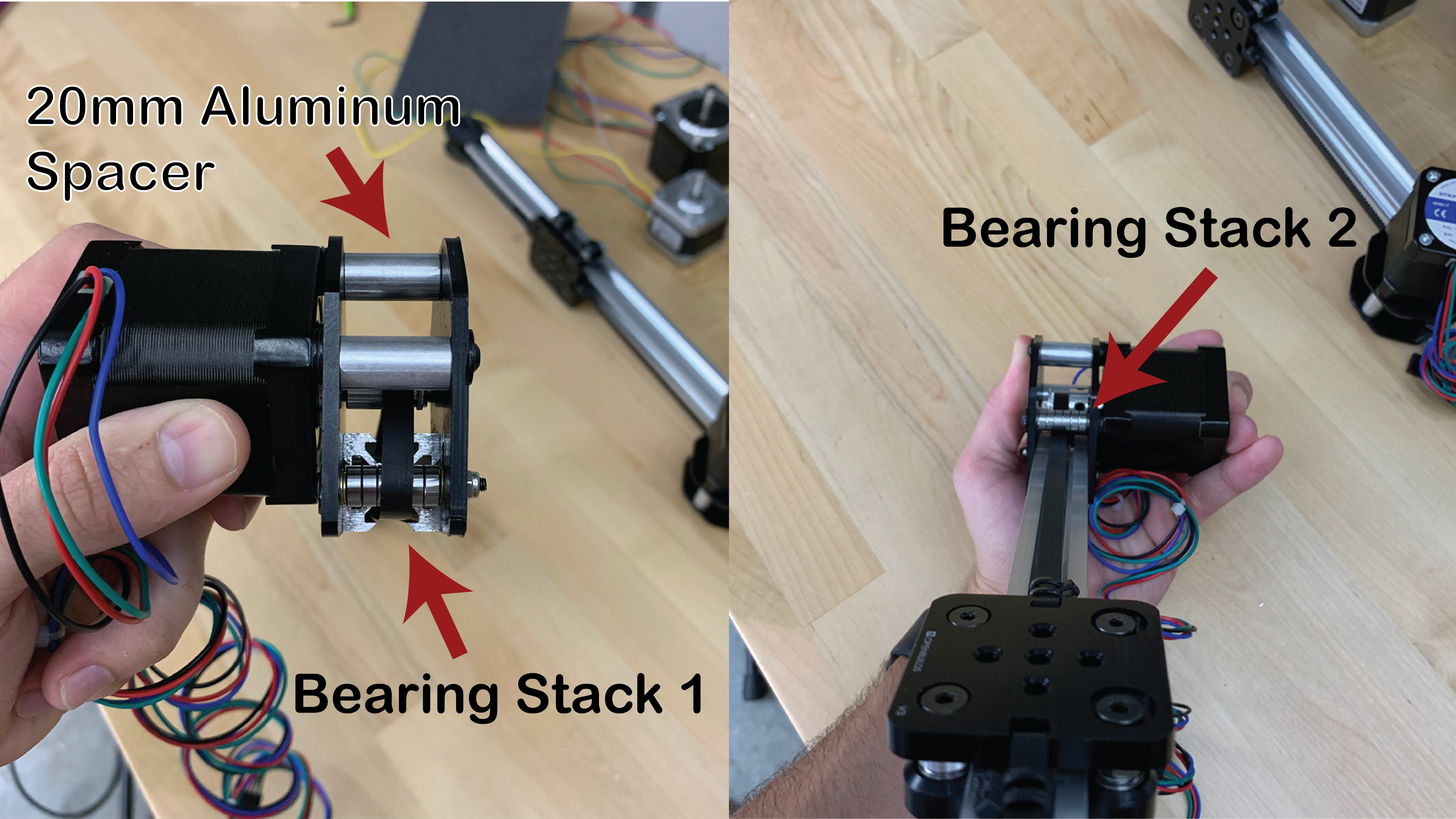
- The motor with a 20T timing pulley is attached to the opposite end of the smooth idler, using an Openbuild’s Threaded Rod Plate, the X-Axis Motor Plate (a 3D printed part), four M3X32 bolts, M3 washers, and either a bearing stack or 20mm aluminum spacer. Figure 5 illustrates the location of the aluminum spacers and bearing stacks. Each bearing stack consists of six 3x8x3mm Ball Bearings stacked on top of each other. Because 6 of these bearings are only 18mm tall when stacked the last 2mm needs to be made up by sandwiching the bearing stack in M3 washers. Notice how the back bearing stack keeps the belt from rubbing against the edge of the V-rail.
- Finally, the GT2 timing belt is cut to size and connected to the ends of the Mini V Gantry after being snaked around the back of the rail and bearings.
- These steps are repeated to for the second X-axis.
Step 6: Z-Axis Carriage
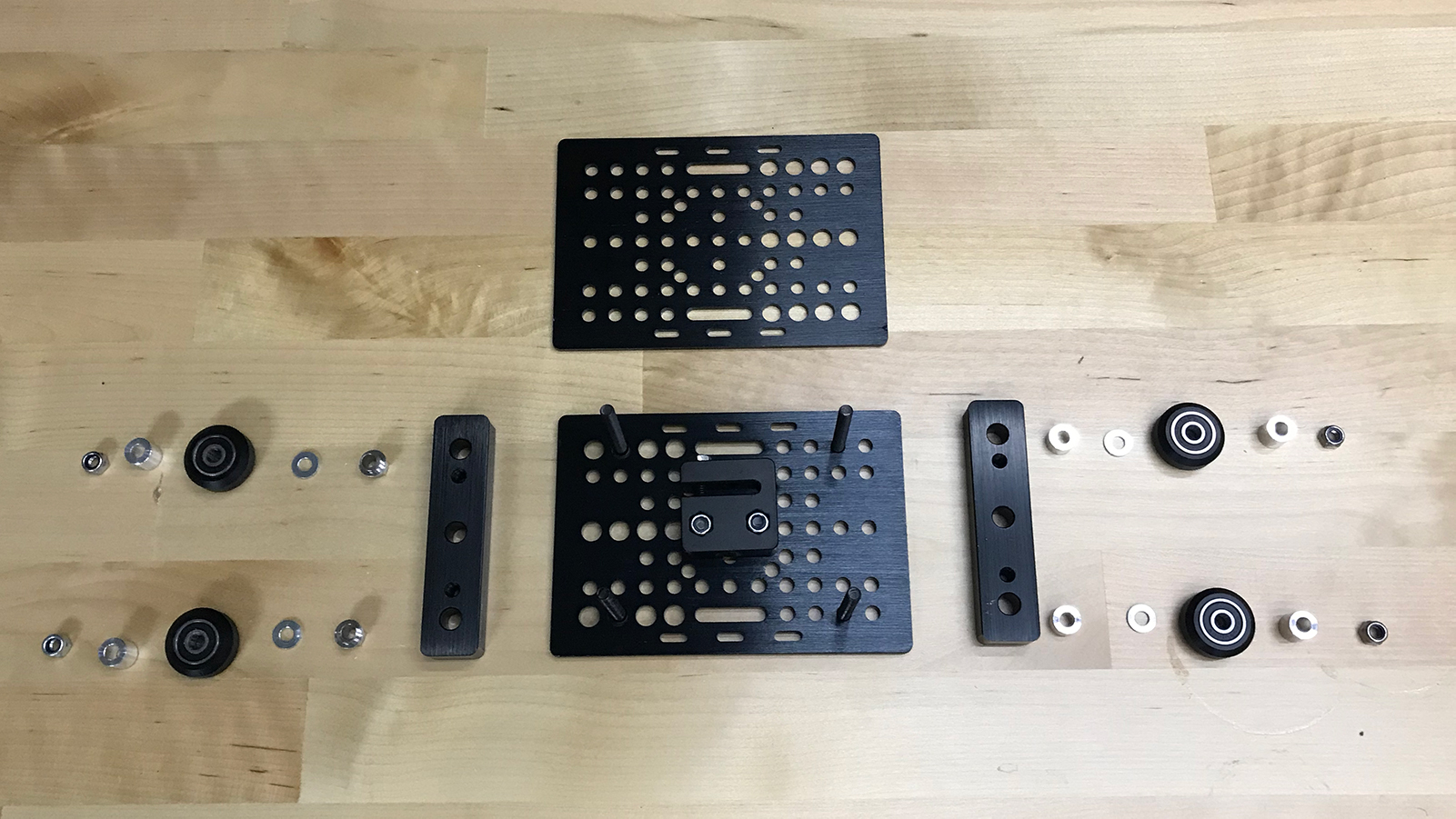
- A nut block is installed in the middle of a V-Slot Gantry Plate (the Z-axis is lead screw driven).
- A 50mm M5 bolt is pushed through the second hole from the outside edge on all 4 corners.
- Two OpenBuild’s spacer blocks are placed vertically on their respective sides.
- On the left (as pictured in Figure 6) one eccentric spacer is placed per 50mm bolt. The flanged side down and mating with the spacer block.
- On the right (as pictured in Figure 6) one 6 mm aluminum spacer is placed per 50 mm bolt.
- On top of each eccentric spacer or aluminum spacer an OpenBuild’s Precision Shim (10x5x1mm) is placed.
- Finally a V-wheel, 9mm aluminum spacer and then the second V-Slot Gantry plate is placed on the 50mm M5 bolts prior to being secured with an M5 nut.
- These steps are repeated to construct the second Z carriage.
Step 7: Attaching X-axis to Z Carriage
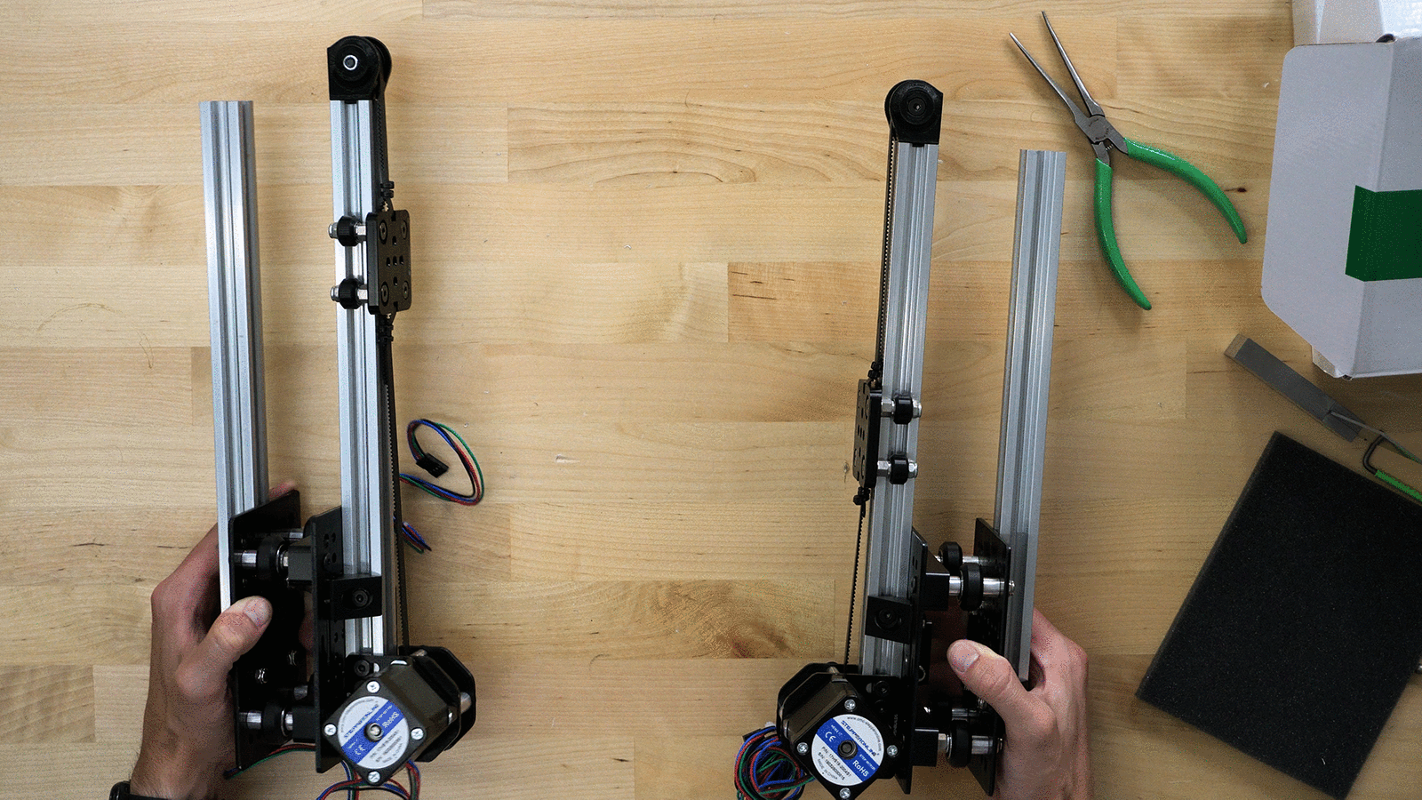
- The two X-axes are connected to separate z-carriages on opposite sides, such that they mirror each other (Figure 7). Right angle brackets and 8mm M5 bolts and nuts are used to accomplish this.
- On the opposite side of each X-axis a 300mm 20x20 aluminum extrusion is also attached. This is where the extrusion drive will ride (more on this later).
Discussion and Feedback
Do you need more help? The best way to get your questions answered by Dr. D-Flo and other DIYers is to post a question on the forum. Click here for the forum topic specific to this project.
Rate this Project: or
Did you encounter broken links or misinformation while reading this article? Please bring these issues to our attention by providing your feedback below.