Overview
The 3D printer needs a reference location known as a home to base all its subsequent movements on. To define a home location, it is important to start visualizing the linear rails as the axes of a 3D graph, with each axis having a positive direction terminating in a maximum and a negative direction ending in a minimum. For simplicity, let’s say this home location is at the minima of the x,y,z axes or (0,0,0). When the power is turned on how does printer find these minima? This process is known as homing and can be accomplished by placing a sensor on each axis, which are triggered when the carriage reaches the minima. These sensors are known as limit switches or end stops. Limit switches are categorized by how they are triggered.
Types of Limit Switches
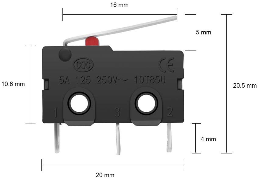
Mechanical Limit Switches
The mechanical limit switch is the most commonly used because of its simplicity and low cost. It is fundamentally a push button that is triggered when its metal spring arm is bumbed. When pressed the switch will either open or close a circuit, depending on how it is wired. When placed on a linear rail the carriage will bump into the limit switch and the microcontroller will sense a change in the state of the switch and will stop stepping the motor.
Optical Limit Switches
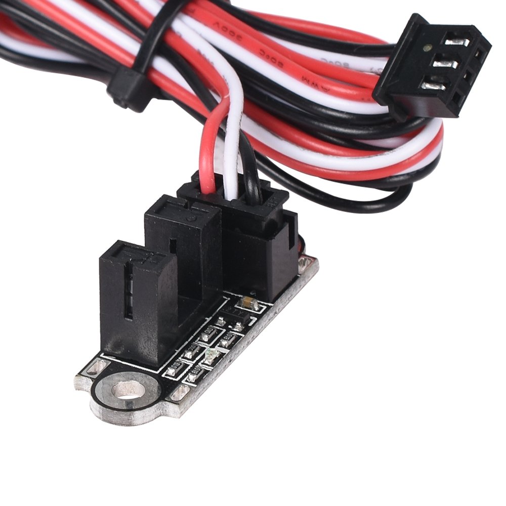
Optical limit switches consists of an LED and phototransistor. When the light path between the LED and phototransistor is blocked the base current of the phototransistor decreases. Most optical switches output a digital high or low signal based on if an obstruction is present, making this limit switch type compatible with many 3D printer motherboards. However, unlike the mechanical switch the optical switch requires an extra wire that supplies power for the LED. With optical limit switches the detection of the carriage is a contactless process. You don’t have to worry about parts fatiguing or wearing out overtime like the spring arm of the mechanical switch. However, interference from ambient light is a slight concern.
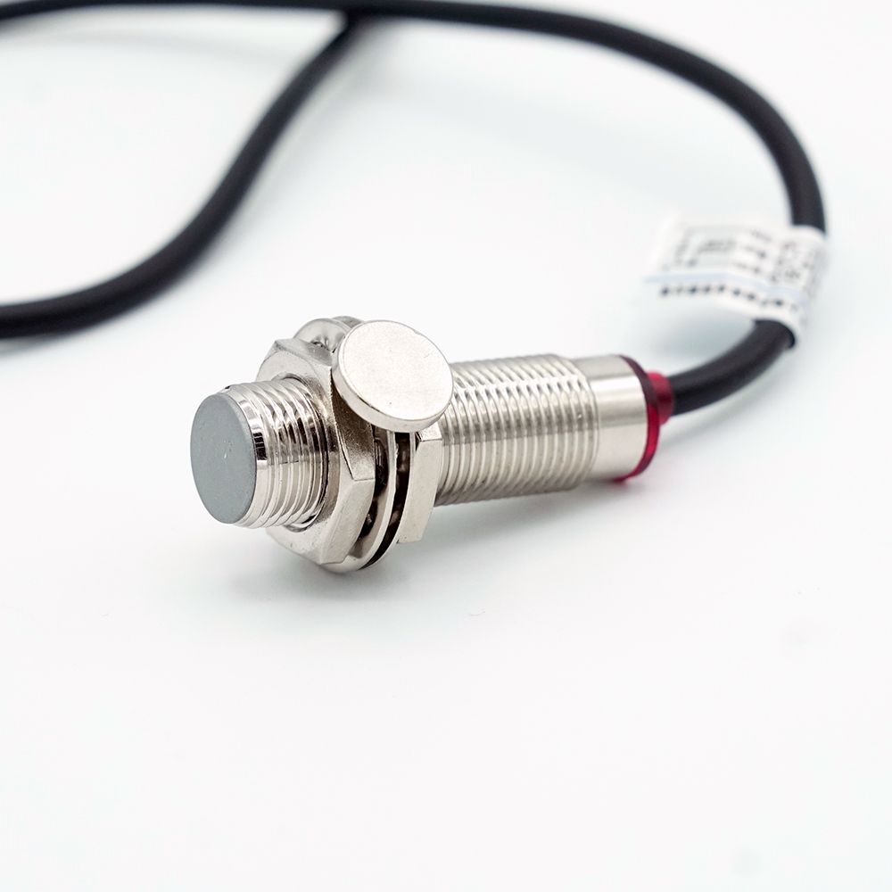
Magnetic Limit Switches
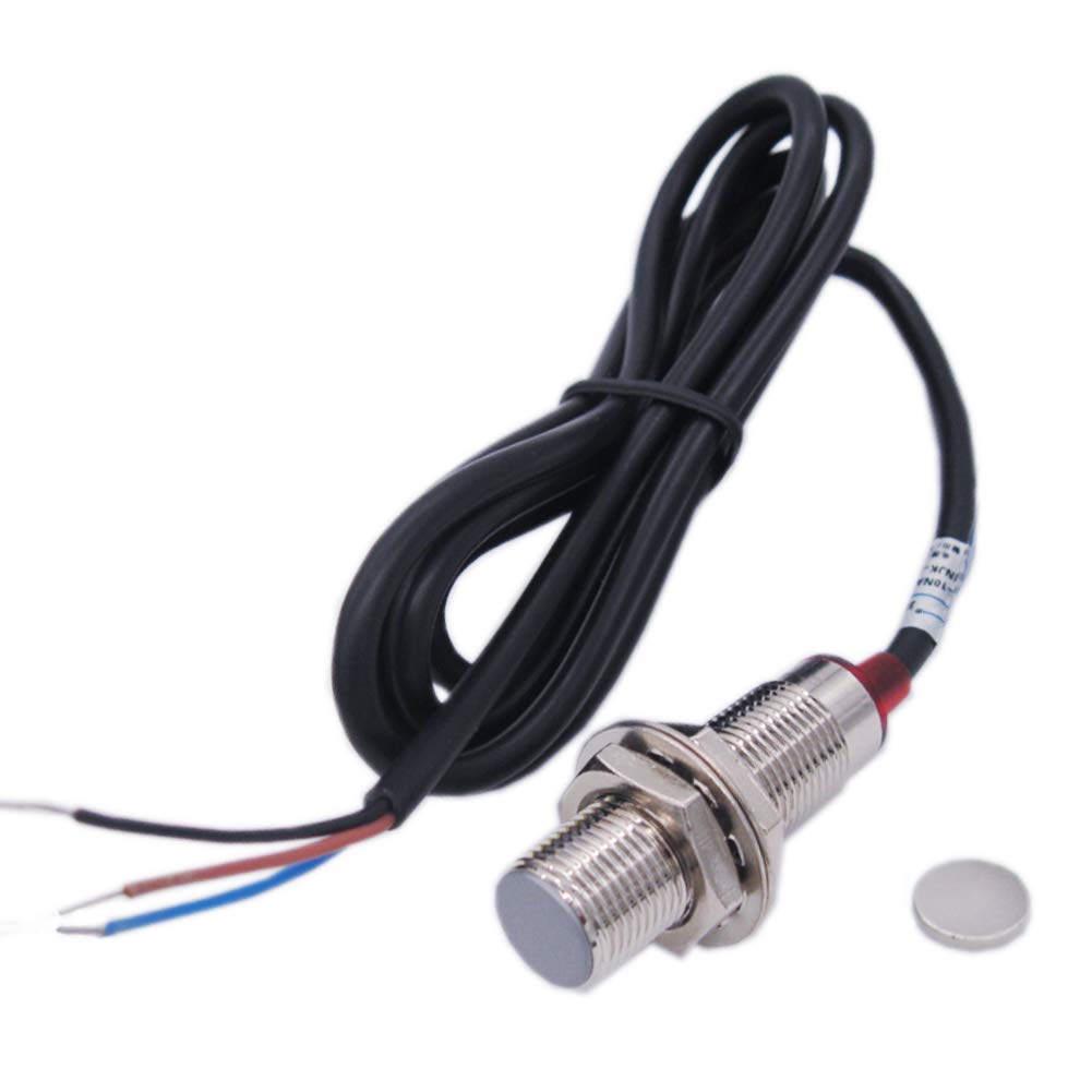
Magnetic limit switches operate on either the principle of electromagnetic induction or the Hall effect. Similar to the optical limit switch Hall based switches are contactless, but instead of detecting changes in light they measure changes in magnetic fields. These types of switches require a magnet to be attached to the carriage. As the carriage moves the magent closer to the minimum and hence the magnetic sensor there will be a distance at which an output signal is triggered. Similar to the optical sensor the Hall sensor needs an extra wire but in this case it’s for a reference voltage required for the switching effect. Unlike an optical sensor, the Hall sensor is not affected by ambient light.
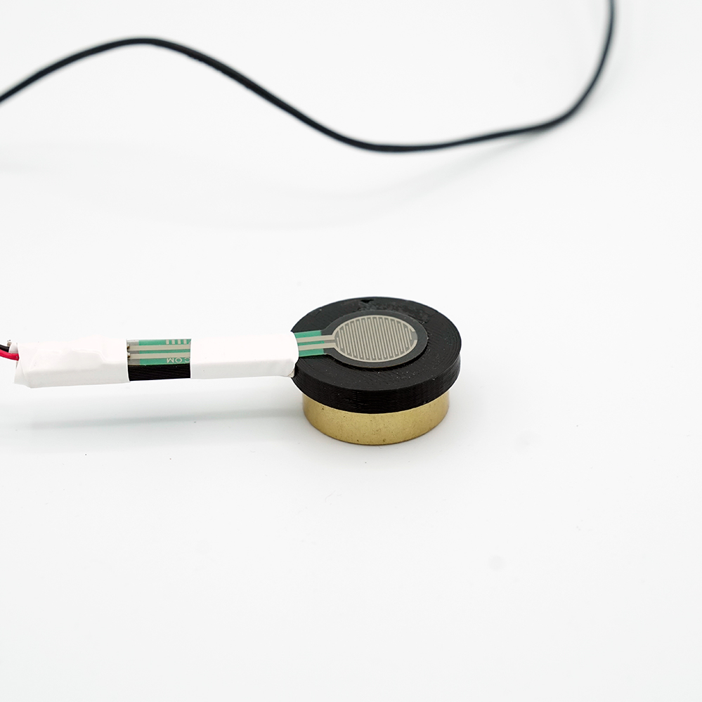
Force Sensitive Limit Switches
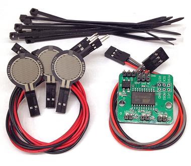
The final type of limit switches is resistive. Force-Sensitive Resistors (FSR), as their name implies, change resistance when experiencing force. With these types of switches an extra controller board is required to measure the changes in resistance of the FSR. This intermediary controller board relays a logic level signal to the printer motherboard. Similar to the mechanical limit switch, the carriage has to touch the force-sensitive resistor for it to be detected. Very rarely is this type of limit switch used to home carriages.
Z Probes
While most 3D printers employ a limit switch on each axis, some designs call for a Z-probe in place of or in addition to a Z-axis limit switch. The most important distance in 3D printing is the distance between the extruder nozzle and the print bed at the start of the print. If this distance is too great then the molten filament will not adhere to the print bed resulting in a failed print. If this distance is too small then the pressure in the nozzle will build up because there is not enough clearance for the filament to be extruded, which could jam the extruder also resulting in a failed print. Similarly to how the minima of the axes can be found with limit switches, the height of the print bed can be found by triggering a force sensitive resistor that is either underneath the build plate or above the build plate at a precisely known distance. The extruder is then brought down to touch either the build plate or the force sensitive resistor directly. This process is called probing and the force sensitive resistor would be called the Z probe. There are different probe types just like there are different limit switches.
External Resources
There are a lot of different ways to successfully build a 3D printer, many of which are not covered on this website. If you want to learn more about limit switches, then click through some of the links below to external websites and forums.
Recommended Products
The table below contains parts specific to this section that Dr. D-Flo uses and recommends. Depending on your printer build these parts may or may not be compatible. It is best to use the products below as a launching point to explore similar products on the linked websites. Affiliate links may be present below (depending on the vendor).