Overview
Electrical motors turn electricity into rotational movement. Outside of the extrusion drive, which is covered in its own section, rotational movement is not particularly useful in 3D printing. Some DIYers have built polar-coordinate based 3D printers where the build platform rotates, but these printers setups are uncommon and still rely on two linear axes. Therefore, the rotational of the motor shaft needs to converted to linear motion. The components that allow rotation of the motor to move the carriage linearly are collectively referred to as the transmission. There are two transmission setups commonly used in the 3D printing: belt-driven and lead screw-driven. While these two types of transmissions are relatively easy to understand, small changes can result in profound differences in 3D printer speeds and accuracy. This section is just a small primer on this deceivingly complex topic, so take the time to read through the external resources below if you are sourcing your own 3D printer parts.
Belt-Driven Transmission
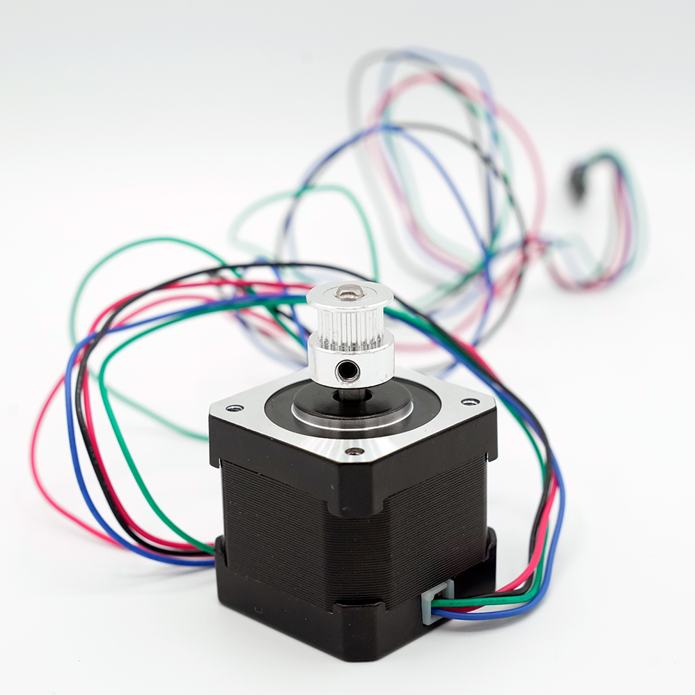
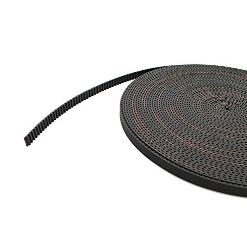
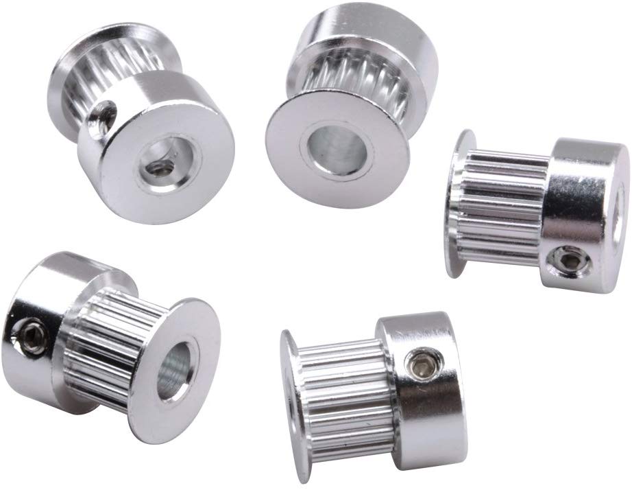
In belt-driven transmission, a synthetic rubber belt reinforced with high-tensile fibers (Kevlar, fiberglass etc.) is connected to both ends of a carriage typically in a closed loop. A specialized pulley, known as a timing pulley is inserted into this loop. The timing pulley has pockets cut into it that match the prolife of teeth present on the belt. When a motor turns the timing pulley the belt moves. In an appropriate linear rail system where the movement of the carriage is restricted to one direction the carriage will move when the belt moves. The timing pulley and belt come in a variety of widths, teeth profiles, and pitches (the distance between consecutive teeth). For 3D printing, the GT tooth profile is optimized to prevent backlash or lost motion when motor reverses the direction of the pulley. The most common belt width and teeth pitch for 3D printing are 6mm and 2mm, respectively. Industrial CNC machines use belts with larger widths and pitches because they have to move carriages significantly heavier than those found on 3D printers. The timing pulley comes in a variety of different diameters. Intuitively, the larger the diameter of the pulley the greater the circumference, which means that more belt will be moved per rotation of this pulley.
The speed at which a carriage will move in a belt-driven setup is not only dependent on the speed at which the motor turns but also the circumference of the pulley. The circumference of a timing pulley is usually reported by the number of teeth. A 16 tooth (abbreviated as 16T) timing pulley would have a smaller circumference than a 60T timing pulley. Intuitively, larger diameter pulleys will have larger circumferences and move more belt per rotation. In 3D printing where high carriage speeds are common a 16Tor 20T pulley is used. Using too large of a pulley can be detrimental to the resolution of the 3D printer but this will be discussed later.
Lead Screw-Driven Transmission
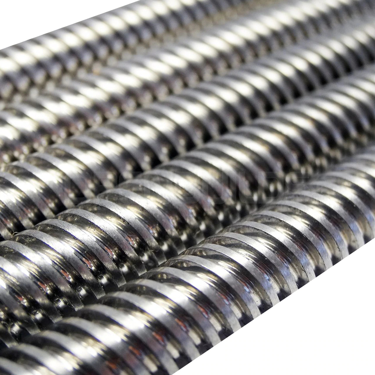
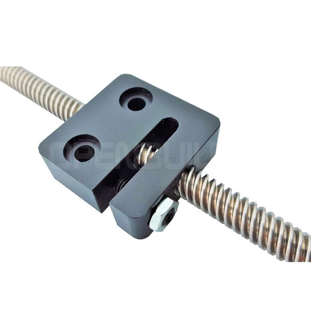
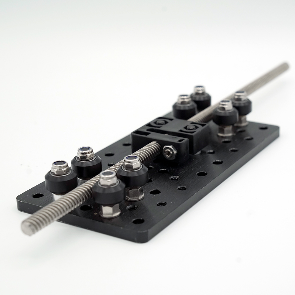
Lead Screw-driven transmission is fairly analogous to how a nut translates up and down a bolt as the bolt is spun. If the nut is kept from rotating as the bolt spins then the nut’s motion is purely linear. Again, this is why it is important to have a carriage that does not wobble as it moves up and down the rail because this wobble would be unaccounted for lost motion. The “nuts” and “bolts” used in linear screw-driven transmission are more complicated. The lead screw (also known as a power screw) has special threading to allow for load transfers of the nut, which would be attached to the carriage, without jamming. The most commonly deployed lead screws in 3D printer builds have the following specifications: 4 starts , 2mm pitch, 8mm Lead. We are not going to unpack all of these specifications, but the 8mm lead means that an appropriate nut would move 8mm every rotation of the screw.
Overall, leadscrew-based transmissions are more accurate than belts, but are slower and more expensive. However, the increased accuracy is not the main reason ACME leadscrews are commonly seen on the Z axis of 3D printers. ACME leadscrews are unlikely to spin on their own, which means when we cut the power to the printer the carriage is not going to drop.
External Resources
There are a lot of different ways to successfully build a 3D printer, many of which are not covered on this website. If you want to learn more about transmission, then click through some of the links below to external websites and forums.
Recommended Products
The table below contains parts specific to this section that Dr. D-Flo uses and recommends. Depending on your printer build these parts may or may not be compatible. It is best to use the products below as a launching point to explore similar products on the linked websites. Affiliate links may be present below (depending on the vendor).