Edited: 1/3/2023
Affiliate Links are present below.
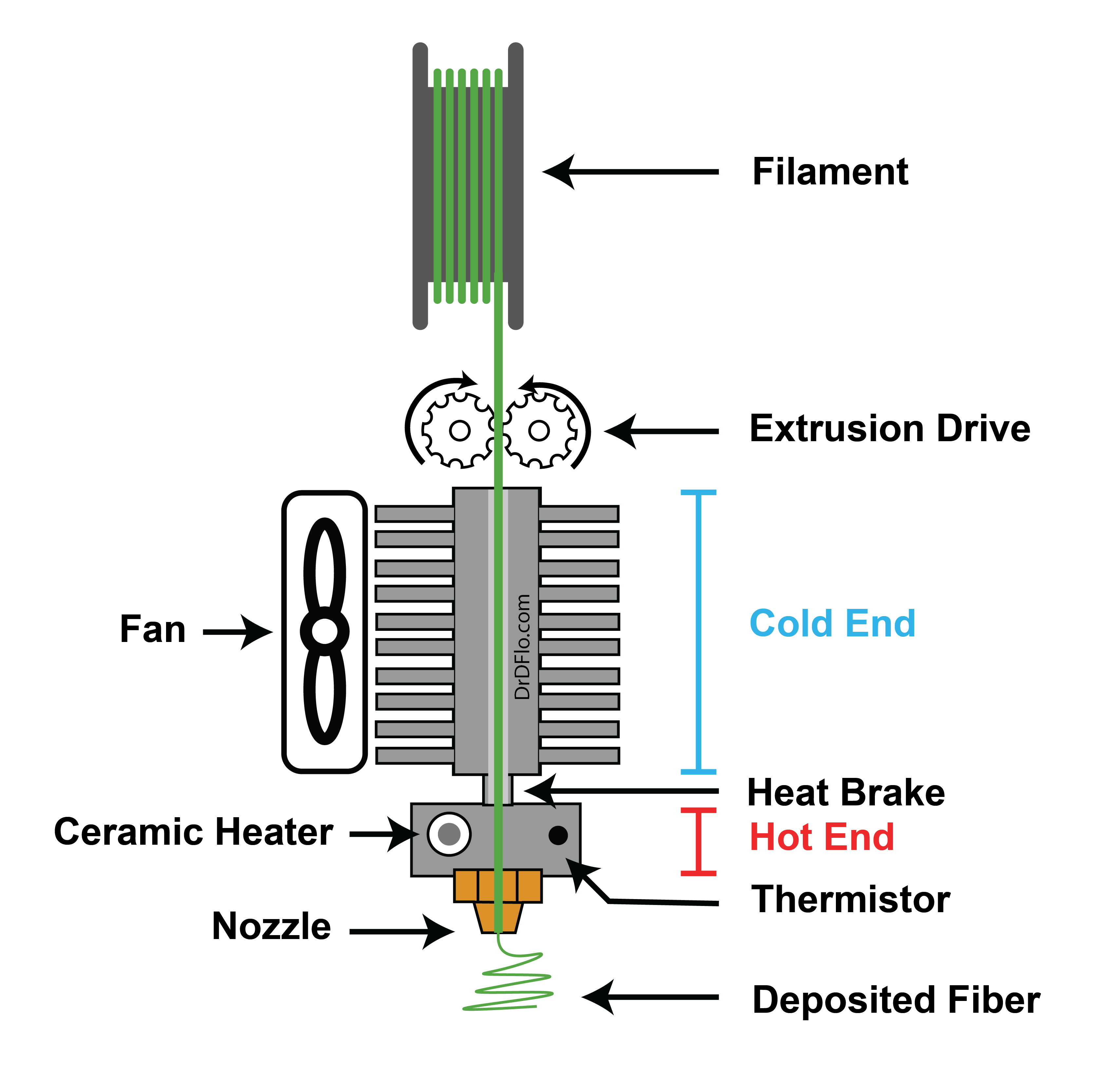
Extruder Anatomy
Overview
The extruder is the defining component of a Fused Filament Fabrication (FFF) 3D printer. It is responsible for heating a thermoplastic filament and forcing the melt out of a nozzle with a small diameter orifice. The extruded fiber is deposited layer-by-layer to ultimately form the printed part. There are four functional elements of an FFF extruder: the extrusion drive, cold end, hot end, and nozzle. This article will cover how these components work together to melt and extrude common thermoplastics. More exotic, high-flow and high-temperature components will be discussed at the end.
Please Note: The extruder has seen the most innovation out of any FFF component in the past 5 years with new and more expensive parts coming out every day. Many of these innovative designs and accessories can cost several times more than older, tried-and true models, but fail to deliver measurable increases in print quality outside of niche purposes (abrasive materials, high flow rate extrusion, etc.). For beginners, it is recommended to start cheap and upgrade as you experiment with more difficult to print materials and geometries. To help, I have created several different configurations for an economy extruder, exotic material extruder, high-flow rate extruder, and high temperature extruder.
Standard Extruder Components
Hot End
The hot end is a thermally conductive metal block between the cold end and the nozzle, which houses a heating element and temperature sensor. The heater increases the flowability of the filament (i.e., melts it) as it passes through the hot end so that it can be pushed out of the nozzle. Hot ends are machined from either aluminum, copper, or steel alloys. Aluminum is the most popular material due to its low cost, lightweight, and relatively high thermal conductivity. However, aluminum has a low recrystallization temperature, which translate to a loss of mechanical properties when printing at high temperatures (> 250 ℃).
Heating Element
To increase the temperature of the hot end to a high enough temperature to melt plastic, a heating element is used. Nearly all extruders use resistive heaters, where electrical energy is converted into heat energy. Early extruders used insulated nichrome wire, which was coiled around the hot end. This setup provided uneven heating because it was dependent on how tightly the wire was coiled and wrapped around the hot end. Today, most extruders use a standardized ceramic heater cartridge. Inside of the cylindrical metal sheath of this heating element is a resistive wire wrapped around an insulating ceramic core. The benefit of this cartridge design is that all heating elements within a certain class will have a known heat output and fit snuggly inside of a set diameter hole. For higher heat outputs, which is needed for high flow rate extruders, larger ceramic heater cartridges can be used. The power output of a heater cartridge is measured in watts with a standard extruder using a cartridge with 25 to 60 W of heating output.
The heating element is the most dangerous component on a FFF 3d printer because if installed or controlled improperly it could melt nearby components, including the wires feeding it power. Therefore, the heating element itself or an electrical short caused by melted wire insulation pose a fire hazard. Fortunately, most heater control loops can sense these issues and cut power to the heating element, but there are still scenarios where the heater can exceed the requested temperature (i.e., thermal runaway). The next evolution of the heating element is the positive temperature coefficient (PTC) heater, which largely solves this thermal runaway problem. As a PTC heater’s temperature rises, so does its resistance. Higher resistance results in less power being consumed, eventually cutting all power to the heater. PTC heaters for standard FFF extruders are designed to operate up to 300 ℃ beyond which their resistance increases greatly. This effectively provides a ceiling to the max extruder temperature independent on the control loop. Also, PTC heaters are flexible and easy to manufacture in different shapes and sizes, which allows them to be wrapped around hot end for uniform heating. The E3D Revo is one of the first extruders to offer a PTC heating element.
Temperature Sensor
A temperature probe located next to the heater cartridge measures the temperature of the hot end, providing regulatory feedback to make sure the hot end stays within a set temperature range. There are two types of temperature probes that are commonly used in 3D printer extruders: 1) Thermistor and 2) RTD (Resistive Temperature Device). The big difference between these two types is that thermistors decrease in resistance with increasing temperatures while RTD have the opposite trend (increase in resistance with temperature). A more subtle difference between these two probe types is that thermistors have a higher sensitivity and are more responsive to changes in temperature than RTDs. However, RTDs have a larger temperature range.
Standard extruders typically come with a 100k thermistor that can measure temperatures up to 300 ℃. If you have the hardware to print at higher temperatures then you will need a PT1000 RTD that can measure up to 500 ℃. At a later date, I will create a guide on the necessary upgrades for high temperature printing.
Silicone Sock and Coatings
The blue silicone “sock” fits snugly over the hot end. All 3D printers move the extruder in at least one dimension, and by moving the extruder you are passing air across the hot end, which will induce thermal fluctuations. The silicone sock acts as an insulator maintaining the thermal stability of the hot end. The sock not only insulates the outside world from the hot end, but it also insulates nearby components, such as a Z probe, from the radiant heat of the hot end.
Heat Break
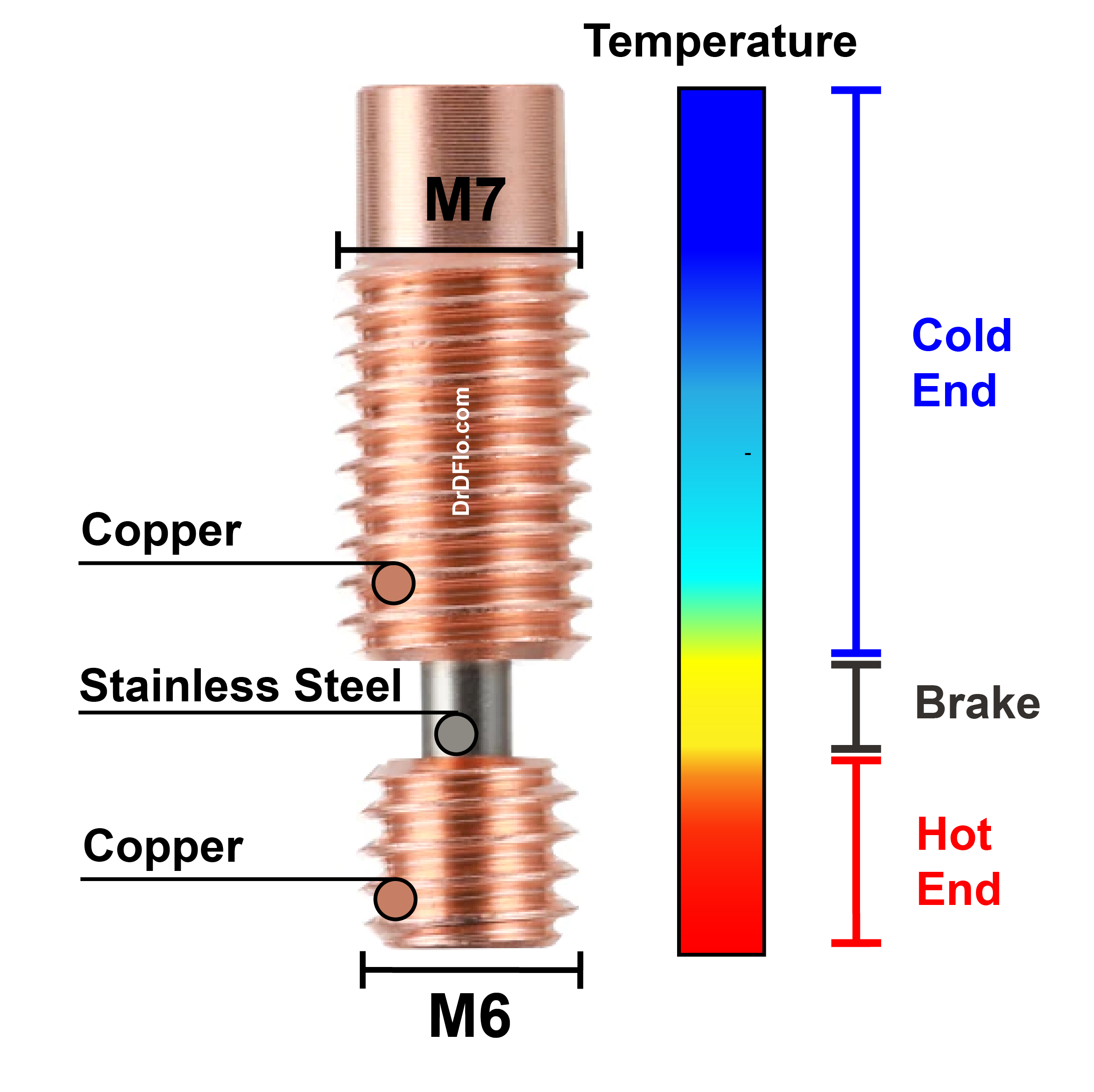
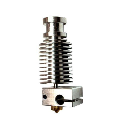
An important and often underrated component is the heat break, which divides the hot end from the cold end (Figure 2). FFF 3D printers require a sharp transition between a cold, solid filament and a molten pool of plastic for two important reasons: 1) The extrusion drive cannot grip and exert its torque on a soft filament – imagine car wheels spinning in the mud. 2) A large volume of melted plastic is less controllable, resulting in oozing after the filament has been retracted away from the nozzle. The premature heating and softening of filaments outside of the hot end is known as heat creep, and it is simultaneously the duty of the heat break and cold end to prevent this. The more thermal energy that the heat break passes on to the cold end the higher the cooling requirements. Therefore, it is best if the heat break can minimize the amount of heat that can flow across it.
The rate of heat transfer is directly proportional to the surface area through which the heat is being conducted and the thermal conductivity between the materials in contact. Heat brakes minimizes both parameters by having a small cross-sectional area and utilizing low thermal conductivity materials. However, heat brakes are constrained by their structural responsibilities, with some heat brakes responsible for holding the hot end and cold end together. With this configuration, the heat brake must have a larger cross-sectional area to prevent it from snapping during a print failure or when swapping nozzles. The heat brake also threads into the hot end and cold end, so insulators, such as plastics and ceramics, are not ideal as they are likely to strip, melt, wear, and/or crack. Consequently, heat brakes are made from metals. Due to its strength and lower thermal conductivity, titanium is well suited to fulfill the functions of a heat brake, but its high costs keeps titanium reserved for premium models. Stainless Steel is most used due to its relatively low thermal conductivity and low material cost.
Cold End
As discussed briefly above, the cold end is responsible for maintaining a cool solid filament that can be easily gripped by the extrusion drive. Minimizing the amount of molten plastic outside of the hot end will also prevent jams and improve the response of the extruder to extrusions and retractions. There are two primary types of cooling systems for cold ends: air cooling and liquid cooling. Cold ends that rely on air cooling feature a fin design where a DC fan blows air across the cold end causing the heat to dissipate into the air. The benefit of an air-cooled design is that it is simple to implement. This simplicity should not be overshadowed as the printhead, where the cold end is located, moves in at least one direction, so the weight and overall complexity of the cooling system should be considered. However, there are several drawbacks of air cooling:
- The minimum temperature of the cold end is limited by the ambient temperature of the printer. This is especially relevant when the printer is enclosed as the cold end may not be able to reach a low enough temperature to prevent heat creep.
- The cold end fan can unintentionally cool the hot end requiring more power to maintain the hot end temperature. A hot end sock can largely eliminate this problem.
- The draft of the cold end can also affect the printed part, specifically for plastics that are sensitive to temperature gradients.
Liquid cooling is the alternative for minimizing the temperature of the cold end. However, having liquid next to a high current heating element should give novices pause. But fundamentally, liquid cooling passes a coolant (typically water) through a thermally conductive block that serves as the cold end. The liquid removes the heat from the cold end and transports it to a radiator or chiller, cooling the liquid for a second cycle. Liquid cooling is largely unnecessary for commodity plastics (PLA, ABS, TPU), and can be a real headache to implement as it can be difficult to route the cooling loops to allow for the printhead to move without causing leaks or kinks. However, when correctly implemented the cold end temperature can be lower than the temperature of the print envelope, which is necessary for high temperature printing.
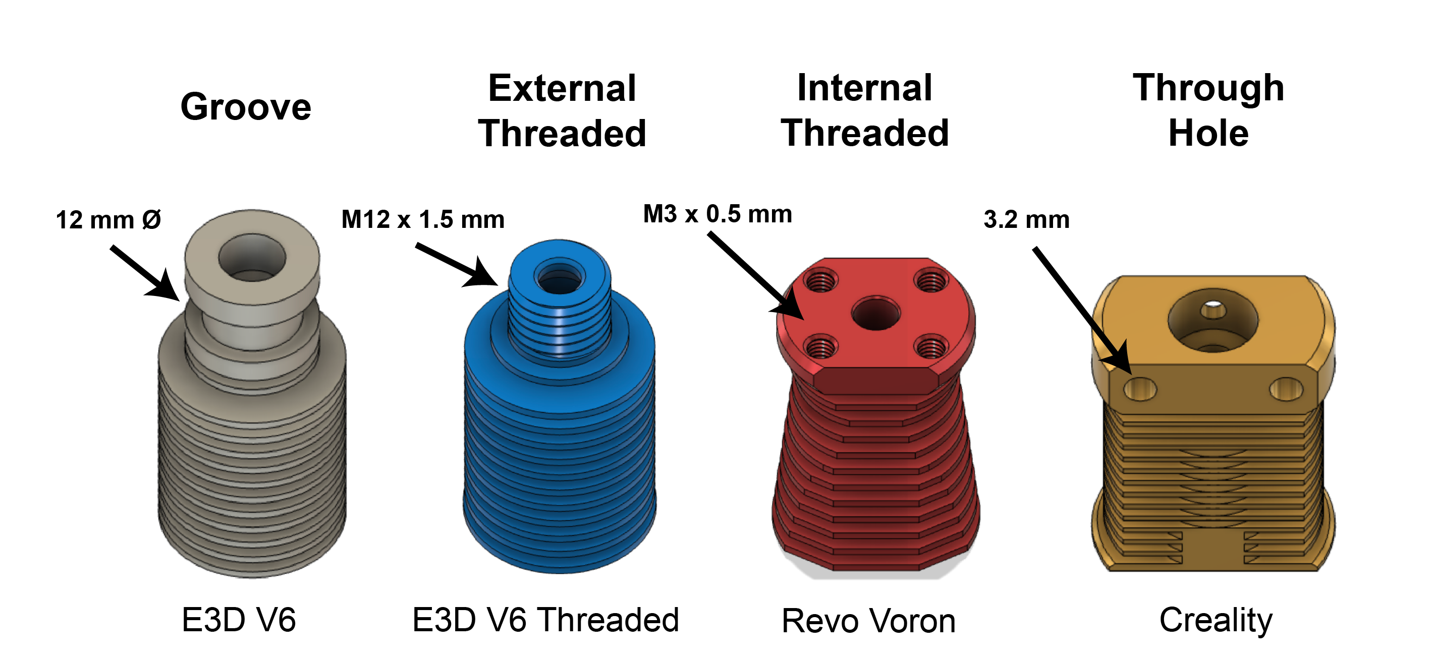
The cold end plays an important secondary role as the mounting point for the extruder to the extrusion drive and/or printhead (Figure 3). For most of the existence of the hobbyist 3D printing space, the standard mounting interface has been the groove mount, which is a 12 mm diameter cylindrical feature. The groove mount was easy to manufacture and cheap but unnecessarily difficult to hold onto. Today, there is a wide selection of different mounting options from external or internal screw threads at the end of the cold end to simple through holes.
Nozzle
The nozzle is the last part of the extruder the plastic touches before being deposited on the build platform. The molten plastic exits the nozzle through a small pin hole of a defined diameter, ranging from 0.25 mm to 1.00 mm (for standard flow extruders). The extruded fiber takes on the diameter of the pin hole, which determines the minimum feature size that can be printed. While this may seem like a straightforward component, there is quite a bit to talk about from the nozzle’s exit diameter, material, and internal and external geometries. All these specifications affect the nozzle’s performance.
Material
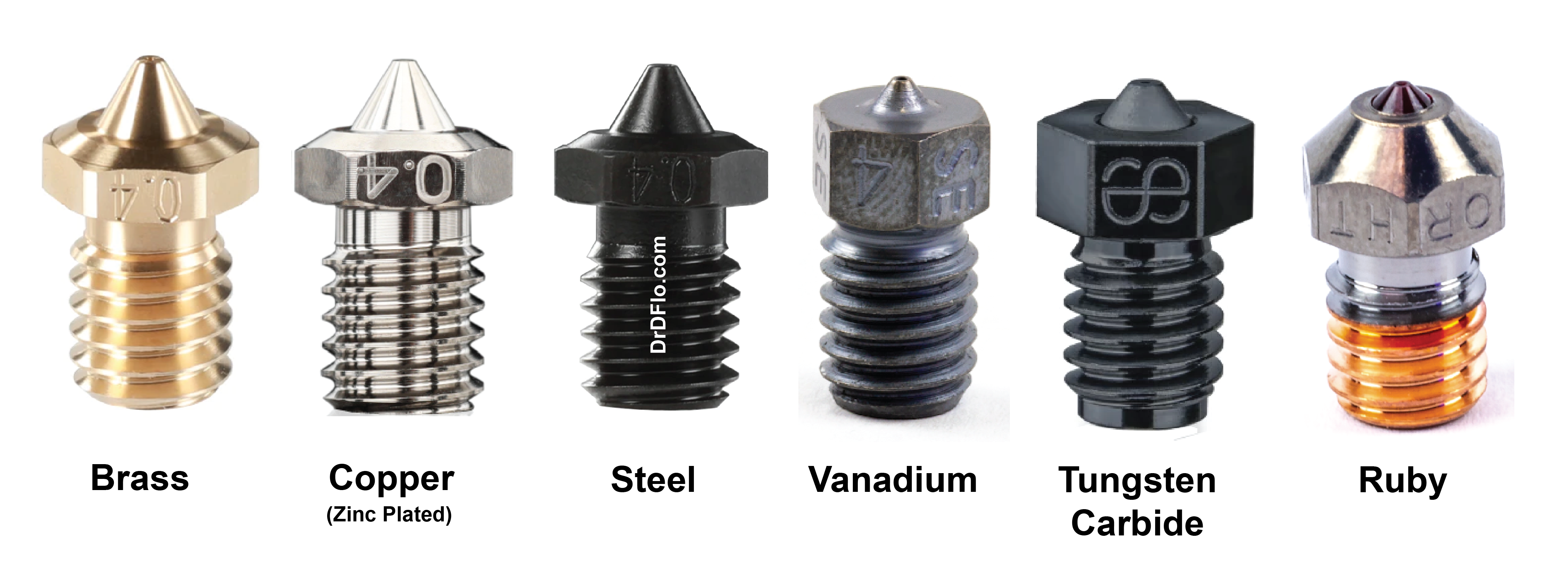
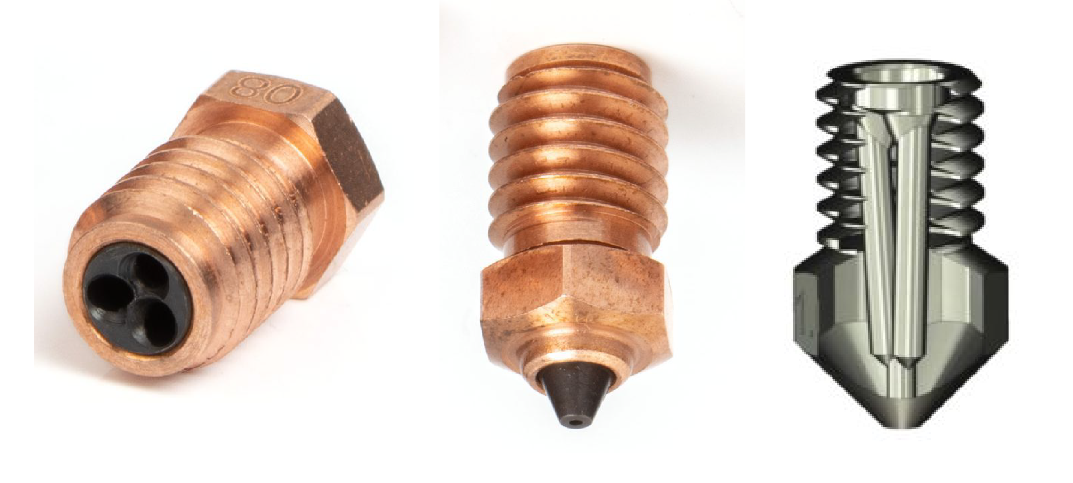
When selecting a nozzle, the other important consideration besides exit diameter is the material the nozzle is made of (Figure 4). The most affordable nozzles are made out of brass because brass is soft and easy to machine, but this softness results in low wear resistance. Composite filaments containing hard and sharp particles like carbon fiber and glass will eat away at the inside of a brass nozzle, increasing the size and irregularities of the pin hole. To print these abrasive composites its best to use a nozzle fabricated from a tougher material. See the table below for nozzle materials and applications.
| Nozzle Material | Thermal Conductivity (W/m*k) | Hardness (HRC) | Max Printing Temperature (℃) | Filament | Cost |
|---|---|---|---|---|---|
| Brass | 105 | << * | 300 | PLA, ABS, TPU, PA, PC | < $1 |
| Copper (Plated with Zinc) | 330 | << * | 500 | All, but abrasive | $15 |
| Hardened Steel | 26 | 60 | 450 | All | $25 |
| Vanadium | 28 | 65 | 450 | All | $35 |
| Tungsten Carbide | 130 | 85 | 550 | All | $50 |
| Ruby | 40 | >> ** | 550 | All | $150 |
**Ruby’s hardness is too high to measure on the HRC
As mentioned, nozzle materials with high hardness (≥ 60 HRC) are required for abrasive filaments, such as carbon fiber or glass-filled composites. A material, such as copper, with a higher thermal conductivity is desired for high flow rate or high temperature printing. Copper nozzles are also useful when significant part cooling is required during the print (e.g., bridging or significant overhangs) because the high thermal conductivity prevents the fans from cooling off the tip of the nozzle. Low heat conduction materials (hardened steel, vanadium) may require increasing the hot end temperature by 5 to 10 ℃.
Due to its high hardness and thermal conductivity, tungsten carbide nozzles are largely considered the last nozzle that you will have to purchase. However, they are expensive and difficult to find at the moment. Ruby-tipped nozzles are an interesting innovation because of this gemstone’s extreme hardness, but their brittleness and high cost are significant drawbacks.
Coatings
Nozzle Manufacturers often modify the base material with a thin coating to achieve corrosion resistance, greater hardness, and/or a non-stick surface to prevent plastic build up on the external nozzle faces. Below are some of the most popular coatings and their benefits:
- Poly-phobic Tungsten Disulfide (WS2) Coating – low friction and repels polymers to prevent clogging and build up of burnt plastic. This material is heat resistant up to 650 ℃.
- Ceramic Diffusion Coating - 3x hardness compared to hardened tool steel, excellent thermal conductivity, and high temperature resistance (> 600 ℃).
- Electroless Nickel Plating - heat resistant up 500 ℃ and reduces the adhesion of plastic to the nozzle.
Nozzle Diameter
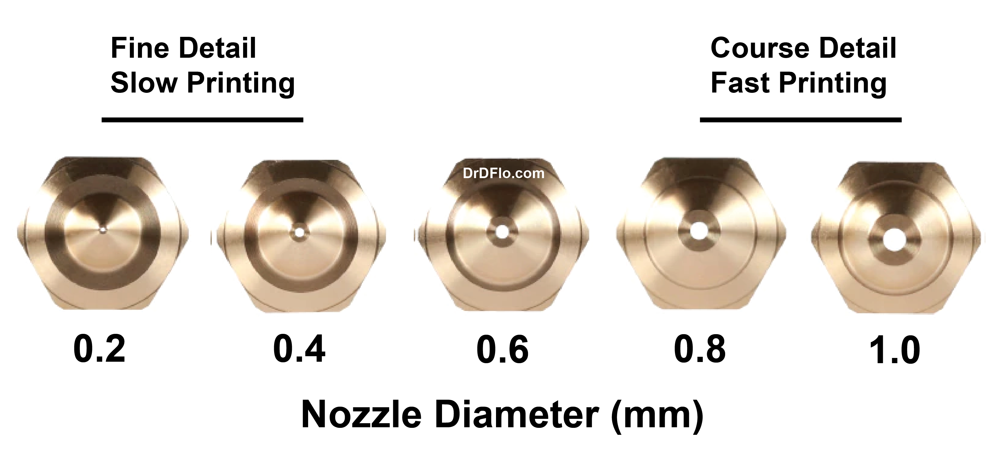
Perhaps the most important decision when selecting the nozzle is the exit bore diameter (Figure 5). The hot end liquifies and forces the filament out of the nozzle, effectively reducing the plastic’s diameter. The cylindrical molten material that exits the nozzle is often referred to as a road because it is laid down along a set path to form the final part. With FFF printing, there is a tradeoff between the smallest detail that can be printed and deposition rate (i.e., print speed). This tradeoff is determined by the nozzle size. Of course, a smaller diameter (< 0.4 mm) nozzle can reproduce smaller features, but less obvious is that significantly higher forces are required to push filament through a smaller diameter orifice. Often the extrusion drive (discussed below) which can only apply a set amount of force when feeding the filament is the limiting factor of flow rate for small nozzle diameters. For this reason, small diameter (< 0.4 mm) nozzles are best used for printing low volume models with high details. Nearly all 3D printers come standard with a 0.4 mm nozzle as this size balances resolution and print speed. But more recently, the 0.6 mm bore diameter has become more popular because it has twice the volumetric flow rate for only a 50% degradation in print resolution. Larger diameter nozzles have two other benefits over small nozzles:
- Less likely to clog when printing composite and/or abrasive material
- Larger nozzles require less pressure to force out the extrudate, which makes printing flexible filaments easier
External Nozzle Geometry
In addition to different materials and exit bore diameters, nozzles may also be manufactured with special geometries to melt plastic faster or achieve higher detail. To be upfront, the print quality of different commercially available nozzles is indistinguishable to the novice. However, there is some interesting innovation in the space that is worth exploring.
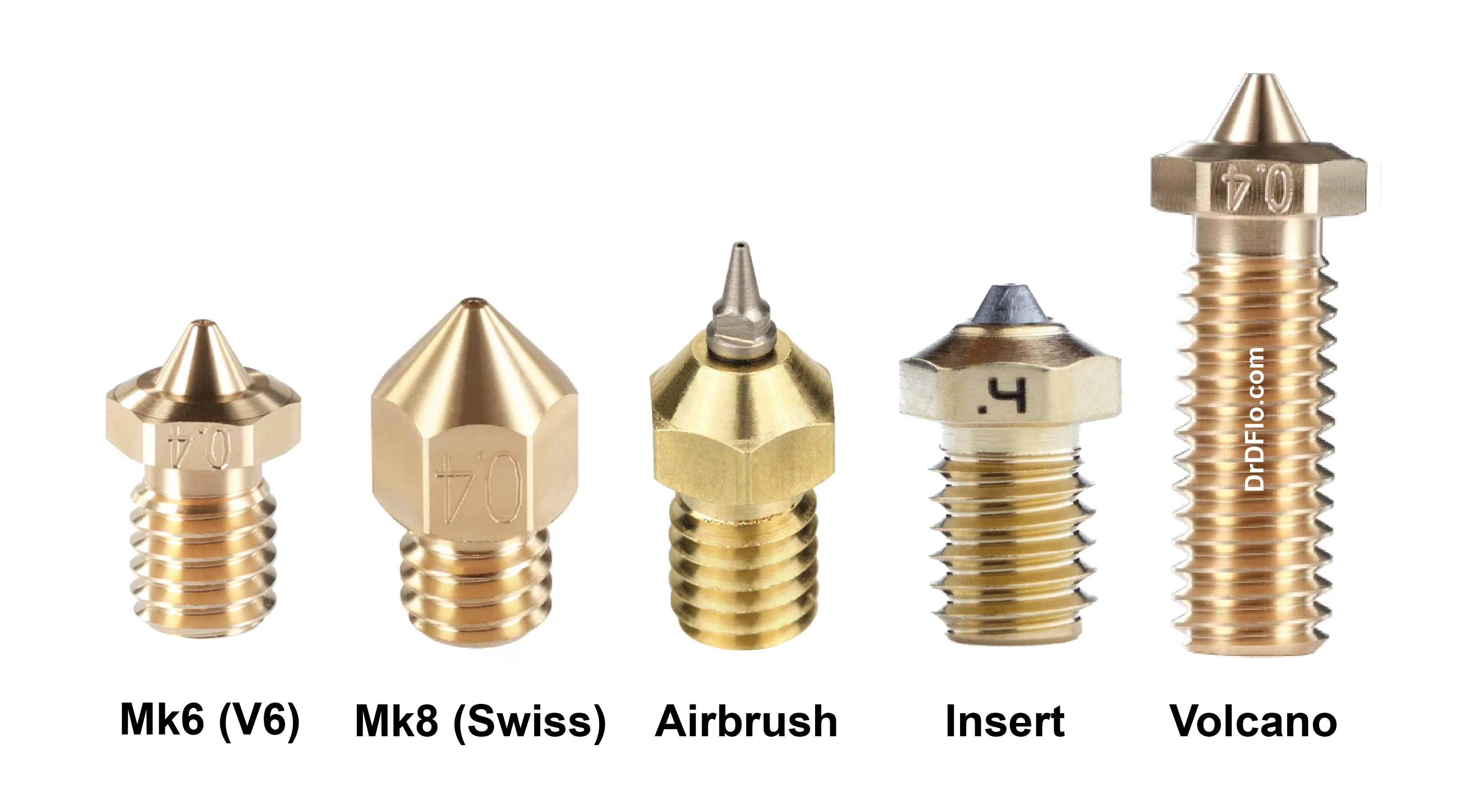
In the early days of hobbyist 3D printing, Makerbot released many iterations of its extruder designs, including the nozzle, while they attempted to optimize cost and performance. The first design was Mark 1 (MK1), the second design MK2, and so on. Mk6 and Mk8 designs saw the most use and their nozzles were widely accepted as the standard. It was helpful that both nozzles shared the same threading: male M6 x 1 mm, and so Mk6 extruders could use Mk8 nozzles and vice versa. Most modern extruders use the M6 x 1 mm thread. If you have shopped for nozzles before then you have likely seen both Mk6 and Mk8 nozzles (Figure 6). Here are the differences:
- Mk6 (also known as RepRap or V6) nozzles have a short cone with a broad end. A shorter nozzle exhibits smaller thermal gradients as it is closer to the hot end. When printing with this nozzle, the hot end will be close to the current layer, which will result in secondary melting of the print. This secondary melting provides better integration between separate roads and often results in a smoother surface (see: ironing). The downside is that small features from previous layers could be softened and lose their details. The pro and con of this ironing effect are largely negated when using an insulating sock on the hot end.
- Mk8 (also known as Swiss) nozzles have a long cone that tapers to a sharp point. The hot end and the thermal mass of the nozzle are farther away from the print and are less likely to induce secondary melting, which will preserve printed details. However, the extruded plastic will have a lower temperature than the hot end due to the nozzle’s length. This could result in slightly degraded mechanical properties due to poor road/layer integration especially when using a part cooling fan. Mk8 nozzles constructed from a copper alloy or another material with high thermal conductivity would mitigate this issue.
Please note: When switching between Mk6 and Mk8 nozzles, be sure to calibrate the offset between the nozzle and the bed as the MK8 is 3 mm longer than the Mk6.
Either the Mk6 or Mk8 can be modified to be an airbrush (AB) nozzle. AB 3D printing nozzles were invented by René Jurack and feature long-drawn-out tips similar to paint airbrush nozzle (for some models, paint nozzles are actually used!).The benefit of this design is that for high detail prints, the thermal mass of the hot end will be farther away from the print, like the Mk8 but more extreme. This spacing also allows for more air from the part cooling fan to reach the recently extruded plastic and cool it before it starts to sag or lose position. The AB nozzle is best suited for printing PLA, a plastic that tolerates temperature gradients and part cooling well. While the AB nozzle was a unique innovation, FFF 3D printing has never been well suited for prints with small details (< 0.4 mm), and with cheap high resolution resin printers available attempts at increasing the resolution of FFF have largely stopped. However, the way in which the AB nozzle was constructed from drilling and tapping the exit bore of a Mk6 nozzle and screwing on a paint airbrush nozzle inspired a new class of nozzles: insert nozzles.
Insert or BiMetal nozzles are where the tip is constructed from a different material than the body of the nozzle. The benefit of this design is that that the body can be constructed from either brass or copper, which are materials with high thermal conductivity but are also soft. The tip can be formed from a hard material such as steel. The tip has a small cross-sectional area, so steel’s significantly lower thermal conductivity will not affect the uniform heating of the filament even at the tip. But the tip will maintain the precise diameter of the exit bore even in the presence of abrasive composite plastics. The tip may screw on or is permanently pressed into place. The former allows for the nozzle diameter or material to be changed without unscrewing the nozzle from the heat block. Gemstone nozzles are always insert nozzles, so pay attention to the material of the body.
Finally, nozzles with long threading are known as Volcano nozzles. This extended length provides more time and surface area for heat energy to conduct from the hot end to the filament. These nozzles are designed for high flow rate applications and will discussed in more detail below. Please note: These nozzles are paired with a larger hot end and are NOT compatible with a standard extruder.
Internal Nozzle Geometry: Taper Angle
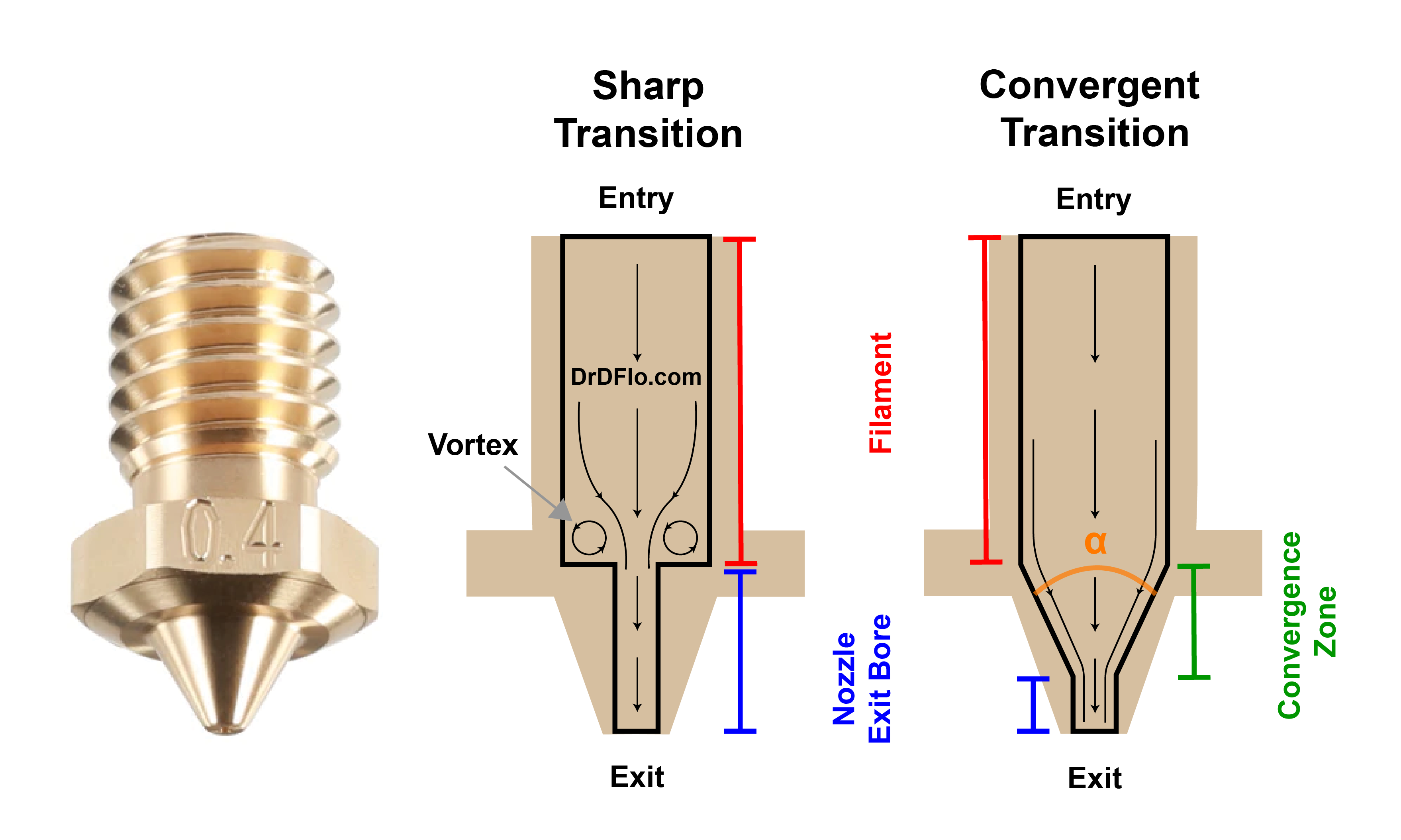
Often what separates a high-quality genuine nozzle and low quality knock off is the internal geometry. Put simply, non-ideal geometries are easier to manufacture and thus, cheaper. Polymer flow through a restriction (i.e., a nozzle) is surprisingly complicated, requiring analysis of rheological and thermodynamic processes. To be brief, we will focus on the most important feature: the interior taper angle but expect a more in-depth article in the future on this topic.
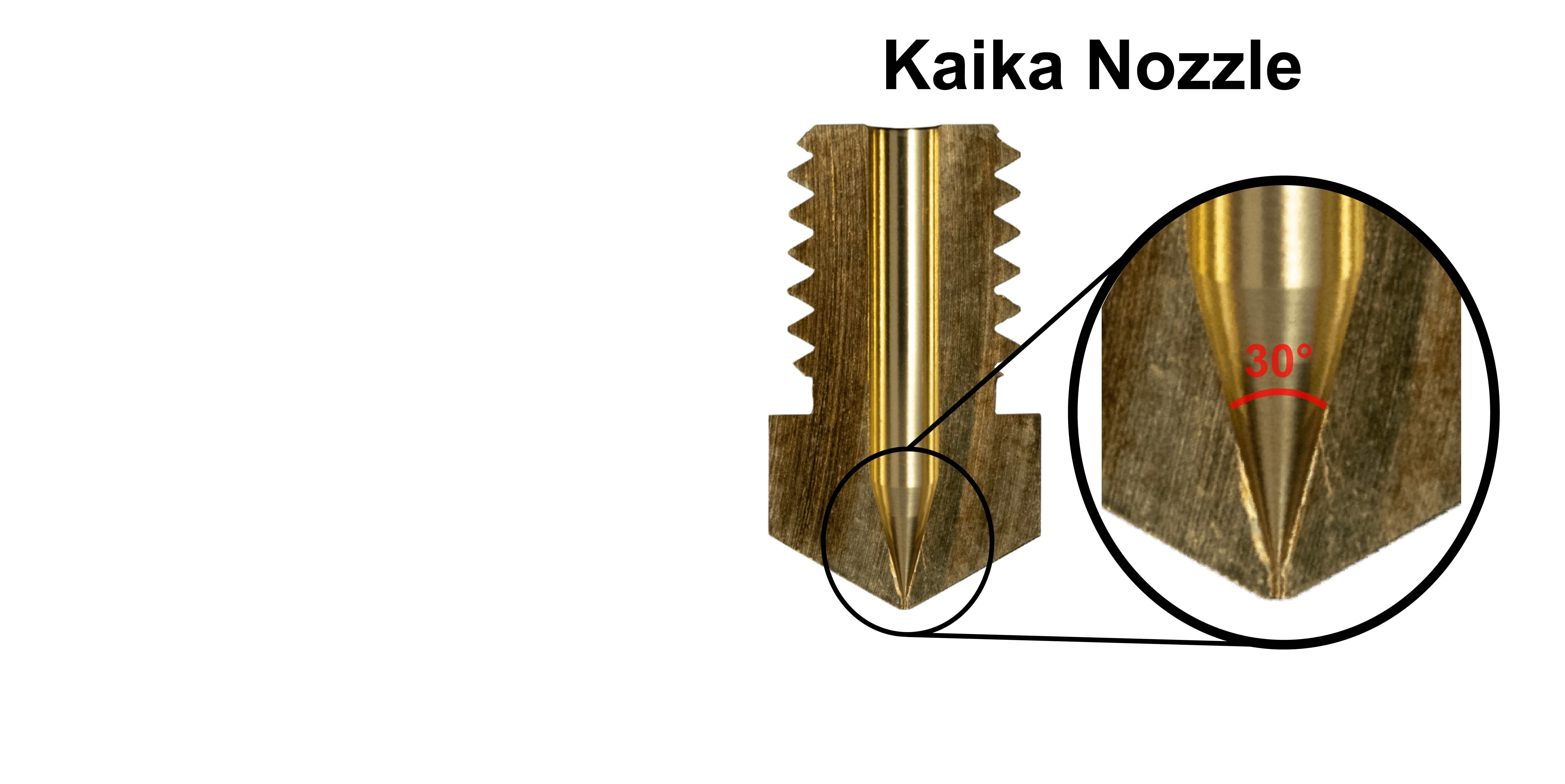
The nozzle must reduce the 1.75 mm filament to a smaller diameter to print fine features. A sharp transition from the filament diameter to the exit bore diameter can result in irregular flow (e.g., vortexes) and back pressure, which requires more extrusion pressure and causes flow instability. Ideally, the transition to the exit bore diameter would be a long and steep taper. The angle of this taper, α, should be less than 30° to prevent secondary flows (Figure 7). However, drilling is the cheapest method for forming holes, and standard drill bits have either a 118° or 135° point. Special, more expensive, tooling is required for angles less than 30°. Consequently, cheap nozzle manufacturers often skip this custom tooling.
So, how does the printing performance of two nozzle with different tapper angles compare? Well, Satoshi T published an article on Medium, where they tested the new Kaika nozzle, which has an internal taper angle of 30° (Figure 8). For a constant extrusion pressure, Satoshi was able to achieve a 20% higher flow rates than E3D nozzles with 60-70° tapers. The 60-70° taper angles on the E3D nozzles are close to ideal as E3D has attempted to optimize taper angles with nozzle cost. The Kaika nozzle is expensive at $35 per brass nozzle. It would be interesting to see how the Kaika nozzle compares to a cheap clone with an even larger taper angle.
To determine the taper of your nozzle without cutting it, perform a cold pull and inspect the end of the filament.
Internal Nozzle Geometry: Core Heating
With a standard nozzle, the outside of the filament is heated by the internal wall of the nozzle. The heat is conducted towards the center of the filament. Plastic has a low thermal conductivity, so it takes a relatively long time for the filament to reach a uniform temperature. If the filament does not have time to melt completely, then the nozzle will clog. Ultimately, this is the limiting factor for extrusion speeds (i.e., flow rate). If the heat has less distance to travel, then the plastic’s low thermal conductivity would be less problematic. This is the logic behind 3D Solex’s core heating technology (CHT), which is composed of a three channel insert that is pressed into a standard nozzle (Figure 9). When the filament runs into this insert it is divided into three separate fibers with smaller diameters that are easier to melt. According to 3D Solex, this nozzle is capable or melting 25 to 65% more plastic than a standard nozzle. This nozzle is ideal for high flow rate printing, which is discussed in more detail below. To learn more about how this nozzle stacks up against the competition check out CNC kitchen's head-to-head comparision.
Maintenance
Poor quality or contaminated filament could clog the nozzle. There are several different methods to clear the blockage, but it is suggested to first extrude a nylon or cleaning filament, such as this one, at a high temperature (250 – 300 ℃). If the nozzle is still clogged, then perform a cold pull by cooling the nozzle with the cleaning filament loaded to room temperature and then pull the filament out either manually or with a cold retraction of the extrusion drive. An alternative method is to use a cleaning needle that matches the nozzle’s diameter. However, be sure to push the debris all the way out of the extruder or else it will form another block. The needle method is not recommended for nozzles with special coatings.
To change a nozzle due to wear or for a better print speed/resolution, you must unscrew it from the hot end. Fortunately, almost all nozzles follow the “RepRap” style and use a male M6 x 1 mm thread with a 7 mm hex head. Depending on the hot end this may be a one-handed operation, but for E3D V6 blocks or clones then an adjustable wrench or preferably Gripper Wrench by Mandala Rose Works will be required to keep the hot end from moving. The nozzle should be tightened to 1.0 Nm of torque. If you are switching nozzles often, then a torque wrench/screwdriver is recommended. The nozzle will have to be tightened one time further when at 200 C to account for thermal expansion.
Filament Diameter and Voltage
There are two specifications that you have to be mindful of when purchasing an extruder: 1. Filament Diameter and 2. Voltage. Extruder product listings typically appears as follows: E3D V6 HotEnd - 1.75 mm and 24 V. Here the 1.75 mm refers to filament diameter and the 24 V is supply voltage needed to power the hot end heating element.
There are two standard sizes for filament diameters: 1.75 mm and 2.85 mm. The filament section of this guide has a writeup comparing the benefits of these two diameters. If you are building a printer from scratch, then going with an extruder that accepts 1.75 mm filament is advisable because this is the more common filament size. Please note: an extruder that supports 3 mm filament cannot be fed 1.75 mm filament.
There are two common voltages that 3D printers run on: 12 V or 24 V. All new printers should be built to run on 24 V, and this includes picking a 24 V extruder. 24 V is far superior to 12 V and you can read all about it in the power supply section.
Extruder Purchasing Guide
There are a lot of different extruders on the market, but four designs stand out: V6, Revo, Mosquito, and Dragon. Read about the pros and cons of each model below.
E3D V6
E3D Revo
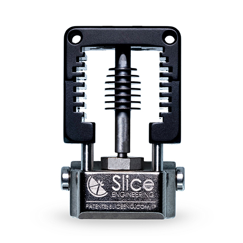
Slice Engineering Mosquito
TriangleLab/Phaetus Dragon
E3D V6
The V6 is the oldest extruder design of the four and has really stood the test of time. The V6 has the most accessories and almost every printer on the market is compatible out-of-the-box with this extruder. If you cannot natively install the V6 on your printer, then there is definitely an aftermarket bracket to help you.
The one notable issue with the extruder’s design is that it relies on the heat break as a structural member. It holds the hot and cold ends together. To prevent heat from spreading to the cold end you want the heat break to be as thin as possible, but this is not possible with V6’s design. If the heat break is too thin, then the V6 would snap if the extruder experienced any force during installation or when changing nozzles. Therefore, the V6’s heat break is quite thick and can suffer from heat creep (as discussed above).
While the “groovemount” of the V6 is widely accepted in the industry, it is difficult for the DIYer to design a mount that properly grabs onto the top of the extruder. Also, if not tightened down properly, the V6 can spin, which can stress the heater and thermistor wires. A rigid mount that uses threaded holes would make it much easier to build a custom printer around a V6.
Even with those drawbacks, the price of V6 is the most competitive and is still the most commonly used.
E3D Revo
The Revo is E3D’s answer to the growing competition in the extruder space. The design is radically different than all other offerings with a novel quick-change nozzle and PTC heating core. The Revo is offered with several different cold ends (and mounting configurations), including the normal V6 cold end, a Voron style, a Creality-compatible variant, and a new micro version constructed from titanium. The PTC heating element was constructed to wrap completely around the hot end, providing uniform heating. As discussed in the hot end section, PTC heaters cannot overheat but are quick to achieve their target temperature.
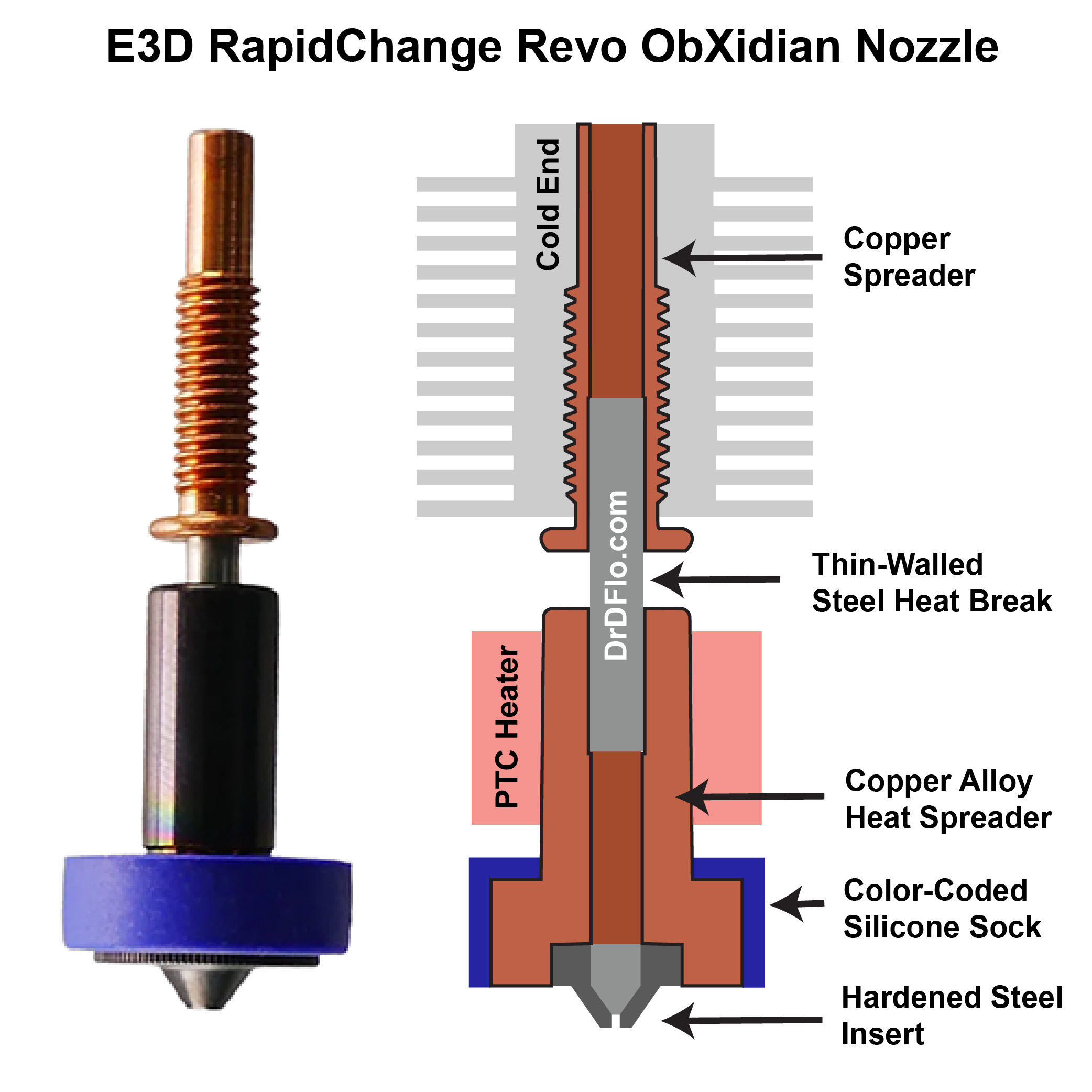
Perhaps the best quality of life improvement is the most controversial: the quick-change nozzle. This design combines the nozzle with the heat break, allowing for the nozzle assembly to be quickly swapped without a tool or heat tightening. This is a major achievement, but the controversial part is a combination of the cost and E3D announcing that they will protect this patented design (i.e. no clones). E3D is asking $23 (at the time of writing) for a 0.4 mm brass nozzle + heat brake assembly, which is a significant markup from buying these two components individually. E3D basically just presses them together, so there is not much value added when assembled. This is a bit disappointing because E3D willingness to allow others to clone and tweak their V6 extruder is what pushed innovation while lowering costs in the 3D printing space (see E3D's response here). But it is difficult to pay for reserach and development when you cannot reap the premium prices for novel designs.
While the nozzles are pricey, the base Revo and its variants are reasonably priced coming in at under $100. The best approach is likely to buy the new abrasive resistant ObXidian nozzle, which is approximately twice the cost of the brass one but should last much longer. Also, unlike other hardned nozzles that are constructed completely from steel, the ObXidian is constructed from a copper alloy for high thermal conductivity with a steel insert (Figure 10 and see video here).
The Mosquito
The Mosquito by Slice Engineering solves the heat break problem of the V6 by having four insulated rods connect the cold end to the hot end, relieving any kind of mechanical pressure on the heat break. This allows for the heat break to have an ultra-thin wall thickness (~0.1mm), which virtually eliminates heat creep. Also, it is much easier to change nozzles because the rods keep the hot end from spinning, so the nozzle can be swapped with one hand. Unlike the Revo, the Mosquito uses the standard M6 x 1 mm nozzle, unlocking all the different nozzle materials and geometries.
The Mosquito has a unique compact design being 30% (~20mm) smaller than the V6. These height savings give you additional Z clearance for taller prints. But possibly the best feature, is the fixed mounting of this extruder. The Mosquito opted for mounting holes instead of the goovemount, so it can be simply bolted onto the print head.
Trianglelabs/Phaetus Dragon
The Dragon took the DIY community by storm. It was an extruder with the price point of a V6 but had the bells and whistles of a Mosquito, including the impossibly thin heat break and one hand nozzle removal ability. Unfortunately, this was too good to be true as this design infringed on Slice Engineering’s US patents, which lay claim to the bridges that connected the cold end and hot end. These bridges are what remove the mechanical pressure from the heat brake and prevent the hot end from spinning when loosening/tightening the nozzle. Slice pressured all retailers to stop the sale of Dragon hot ends with nearly all models going out of stock soon after. It was within Slice’s right to enforce their patent, but many DIYers were upset by a move they perceived as stemming innovation. It did not help that Slice is charging an arm and a leg for their extruders.
Fast forward to the end of 2022, and the Dragon and its high flow rate cousin Rapido are back in stock both at US retailers and abroad. These new product listings showed the old dragon but without the bridges. It was assumed that the Dragon switched to a structural heat brake like the V6, but purchasers reported that the Dragon came with the forbidden bridges. It seems that TriangleLabs is trying to be less obvious about its patent infringement or perhaps, they found a loophole with a slightly different geometry or material for the bridge.
Initially the Dragon was not going to make the list because of its legal troubles, but it is just too popular to ignore. The Dragon is great value for the individual, but it would not be advised to run a printer farm equipped with Dragons in case components become scarce again.
The high flow rate and high temperature section contain more extruders, so keep reading!
Extrusion Drive
Extrusion Drive Anatomy
It takes quite a bit of force to push molten filament out of a small nozzle that is a fraction of the size of the filament’s diameter. It is the extrusion drive’s job to convince the filament to go into the extruder out the other side.
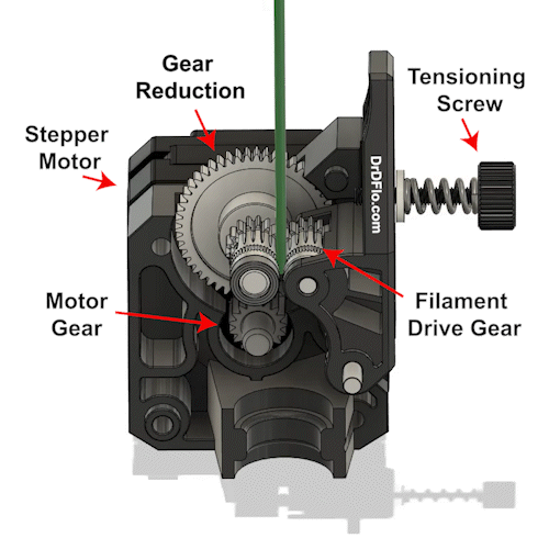
The extrusion drive is powered by a stepper motor that either directly or indirectly drives a gear with ridges or teeth. These sharp features bite into the smooth but hard surface of the filament providing sufficient traction. A second hobbed gear or smooth bearing sits on the opposite side of the filament and confines the filament’s movement to up or down (Figure 11).
A stepper motor requires about 0.7 N-m of torque to properly drive the filament gear(s). Very few small form factor motors have this kind of torque. A larger motor could be used, but heavier motors are not ideal because they can slow down the tool head if the extrusion drive is attached directly to the extruder (more on extrusion drive placement later). Therefore, most extrusion drives utilize gears to increase the torque output of small “pancake” Nema17 motors. 3:1 and 5:1 are typical gear ratio used in commercially available extrusion drives, resulting in 3x and 5x more torque respectively. Keep in mind that higher gear ratios will result in higher torque but also proportionally lower speeds. At some point your printer’s speed could be limited by the gearing of the stepper motor if you choose too high of a gear ratio.
Extrusion Drive Placement
In some 3D printer designs the extrusion drive sits on top of the extruder and moves along with it (i.e., direct drive setup. In other designs, the extrusion drive is fastened to the frame and is connected to the extruder by a long tube known as a bowden tube (i.e., bowden setup). There are pros and cons for both placements of the extrusion drive.
With the bowden tube extrusion drive system the print head can accelerate and deaccelerate faster because the print carriage does not have the added weight of the extrusion drive. This can significantly speed up print time. The drawback for this setup is the increased distance between the hobbed gear that is pinching the filament and the hot end. The longer this distance the less responsive the filament extrusion will be. This hysteresis or lag is amplified when printing flexible filaments, so it’s best to avoid the bowden setup when you expect to print flexible parts.
For the direct drive extrusion system the pros and cons are swapped. You can’t accelerate and deaccelerate as quickly because the carriage has the added mass of the stepper motor but the extrusion and retraction of the filament is more responsive. The direct drive setup is by far the most popular configuration in the DIY community as print quality is usually a top priority.
Recently a third, hybrid configuration for the extrusion drive has been developed, where the extrusion gears sit close to the hot end similar to a direct drive setup, but the motor is located on the frame like a Bowden. How is this possible? Well, the motor drives a long-keyed cable, which is flexible enough to follow along with the print head but stiff enough to translate the rotation of the motor to the extrusion gears. This hybrid configuration is known as remote direct drive, which promises to combine the benefits of Bowden and direct drive with none of the limitations. This is still a new and developing technology that is plagued by several reliability concerns, but these will hopefully be sorted out in the future. Currently the two main manufacturers of remote direct drive are Flex3drive with the G5 Flex Extruder and Zesty Technology with the Nimble Flex.
Extrusion Drive Pruchasing Guide
The designs of all extrusion drives are converging on the Dual Drive technology that was first introduced to the hobbyist market by BondTech. Gripping the filament on both sides allows for consistent extrusion and retraction. All four extrusion drives that I recommend are dual drive: BMG, LGX, LDO Orbiter, and Sherpa Mini/Micro. These extrusion drives may come in several different configurations to mount directly to different extruders. For example, a stanard BMG has a groove mount for the V6 and dragon, while the BMG-M has the bolt on mount for the Mosquito. Below the product listings are descriptions for each drive and differentiating factors.
It should be pointed out that there are 3D printable extrusion drive designs that are significantly cheaper than commercial offerings. The Voron Clockwork is a repackaged BMG dual-gear drive, which cost a fraction of a genuine BMG, but you have to source your own gears and bearings. Clones also exist for many of the designs, which could save you money or could cause a headache if these knockoffs are manufactured poorly.
Bondtech BMG
Bondtech LGX
LDO Orbiter V2.0
Sherpa Mini/Micro
BMG
The Bondtech QR extruder was the answer to the unreliable extrusion that plagued 3D printers in the 2010s. After a couple of iterations, the BMG superseded the QR extruder as a lighter alternative (~210 g including motor). The BMG would go on to be the most popular 3rd party extrusion drive. Today, aftermarket kits allow you to install a BMG extruder on nearly all 3D printers, including those manufactured by the likes of Prusa, Creality, and Ultimaker.
The appeal of the BMG is the dual-drive hardened steel hobbed gears. These gears have the profile of the filament cut into them and with lots of sharp little teeth have a high surface contact with the filament. Both drive gears are actively driven by a 3:1 gear ratio for triple the torque output from the motor.
While ultra-reliable, the BMG does command a high price tag for its gears and SLS-printed housing. This cost does not even include a pancake NEMA 17 motor that is required for operation.
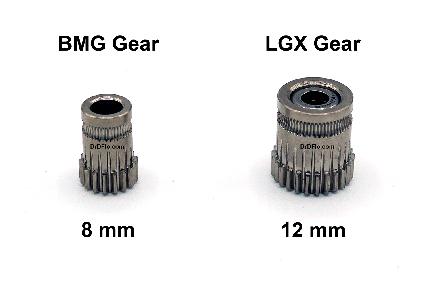
LGX
The Large Gears eXtruder or LGX for short is a separate product line from Bondtech but could be viewed as the next iteration of the BMG. The LGX uses larger drive gears to feed the filament (Figure 12), which translates to more accurate extrusion and retraction especially at high print speeds. When plastic filament experiences high stress (stress = force/area), it will plastically deform and be ground up by the teeth on the drive gear – not good. To decrease this stress, the area that the extrusion drive’s force is acting on can be increased, which is what is accomplished by using larger drive gears.
Nearly all extrusion drives use a tensioning screw to set how tightly the drive gears press up against the filament. Rigid filaments require low tension and flexible filaments require high tension. Improper tension could cause grinding or slipping of the filament depending on whether it is set too tight or loose, respectively. Adjusting the tension screw is a manual process that requires the operator to “feel” when the tension is correct. The LGX uses a new ratcheting system that allows for 6 pre-set tensions to be selected quickly and repeatably for printing a range of soft to rigid filaments. The larger drive gear and ratcheting system only increased the extruder’s weight by 10 g compared to the BMG's (~220 g including motor). If that is too heavy for your application, then checkout Bondtech’s new LGX Lite, which comes with the same large drive gears but only weighs in at 141 g with the motor installed. The only drawback to the lite version is that the tensioning system only has 3 presets (instead of 6).
Even though the LGX appears to be 25% more expensive than the BMG it does comes with a pancake stepper motor and is ready to run out of the box. So the difference in price is much smaller than you may think. The larger gears, tensioning system, and sleek looks are worth the small premium.
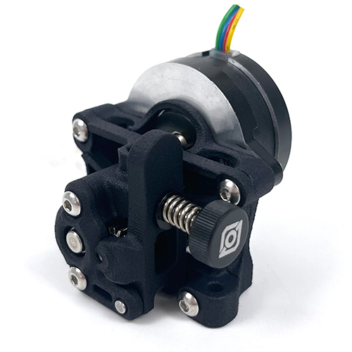
LDO Orbiter V2.0
The LDO Orbiter is a rare example of a Thingiverse design that went on to be successfully commercialized with the help of the original creator, Dr. Róbert Lőrincz. Dr. Lőrincz is incredibly passionate about his designs, and he thoroughly documents his rationale on his website. This will be a quick summary of the features of the new V2.0 Orbiter.
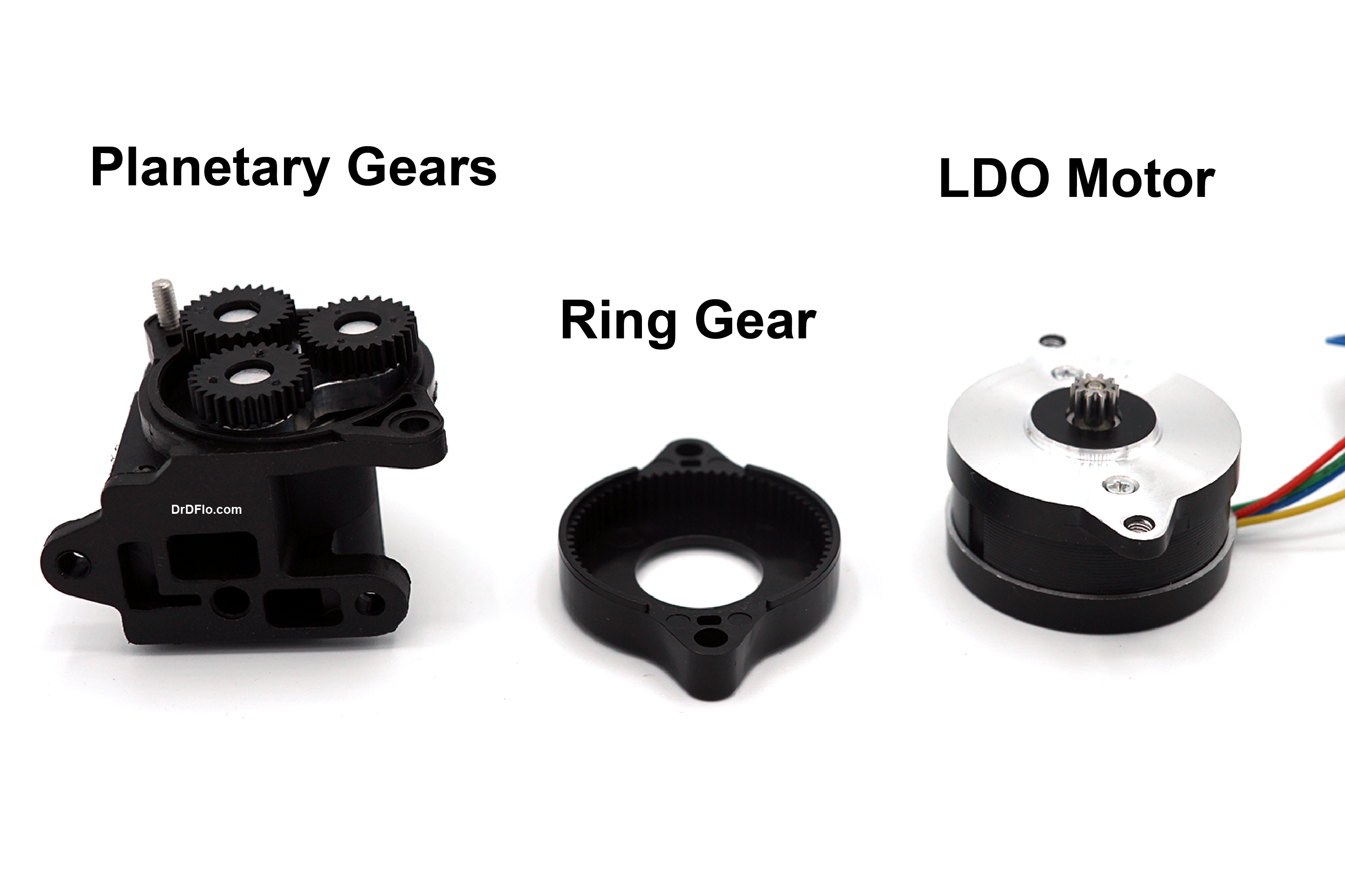
Unlike the BMG, LGX, and Sherpa, which use single stage spur gear reducers (i.e., one small gear turns one large gear), the Orbiter uses a planetary gear box to increase torque. Of course, the planetary gears “orbiting” around the sun gear is where the extrusion drive gets its name. The main benefit of a planetary arrangement over a single stage spur gear is the lifespan. The forces in a planetary gearbox are shared between the three planet gears, and thus, should have three times lower wear compared to spur gears. Most extrusion drives use plastic gears to reduce weight, so wear is a concern.
Compared to previous iterations, the Orbiter V2.0 is lighter (135 g with motor), more compact (11.6% shorter), and is capable of higher extrusion forces (40% increase). But perhaps, the most important improvement is the stainless-steel guide tube that restrict the filament path’s immediately after the drive gears (only 0.2 mm of clearance!). Without this guide tube, previous version had difficulties printing flexible filaments.
The one drawback of this design is the placement of the mounting holes. When a button head cap screw is installed through the hole on the right side, it blocks the door, which is used for clearing jams and cleaning the gear teeth, from opening all the way. This is a minor annoyance, and for the price (~$55), the Orbiter V2.0 is very competitive.
Sherpa Mini/Micro
The Sherpa Mini and Micro are two extrusion drives designed by Annex Engineering. They are open-source models that contain FFF printed parts, but third parties offer injection molded alternatives. The difference between these two models is that the Micro turns the LDO stepper motor 45 degrees to decrease the overall width of the extrusion drive (46 mm wide for Micro versus 51 mm for the Mini). This small formfactor is the reason for the Sherpa’s popularity especially in builds that have multiple printhead (i.e., IDEX), where space is at a premium.
The Sherpa’s performance is hurt by its max recommended stepper motor current of 0.35 A, which limits its acceleration. Acceleration is mostly important for retraction, as the faster the filament can be pulled away from the exit bore the less stringing there will be. However, few if any users have reported issues with the print quality of this drive.
To see most of these extrusion drives pitted against each other in real world and simulated benchmarks, then check out Dr. Lőrincz’s head-to-head article.
High Flow Rate Extruders
The class of extruders that are garnering the most attention right now are high flow rate variants. The need to extrude more plastic per second is a result of faster and more capable DIY 3D printers, such as the VzBoT, Rat Rig V Core, and Voron printers. Also, with the increased accessibility of resin printing, FFF enthusiasts have been less focused on resolution and more on print speed.
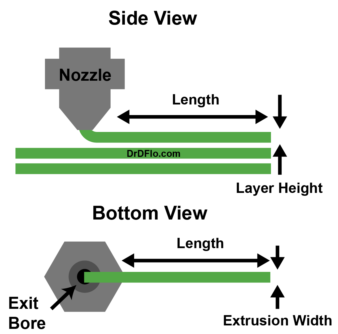
Let’s perform some calculations to determine when to upgrade to a high flow rate extruder. A standard V6 extruder is capable of extruding PLA at a maximum flow rate of 10 mm3/s. To make the calculations simpler, let’s assume that the extruded plastic can be approximated by the shape of a rectangular prism, where the width is the nozzle diameter, and the height is the layer height. The length of the prism will be constrained by the max flow rate of the extruder (Figure 14). Therefore, the maximum print speed for an E3D V6 with a 0.4 mm nozzle printing at a 0.2 mm layer height would be:
(10 mm3 s-1)/(0.4 mm * 0.2 mm) = 125 mm/s
Most consumer 3D printers, including the Ender 3, have an advertised print/travel speed of 150 mm/s or greater, but in 3D printing, where prints are composed of many short movements, high accelerations are needed to consistently achieve these print speeds. It is more realistic for these printers to be operating at speeds around 50-80 mm/s. Therefore, for all but the most extreme printer builds, a standard extruder with a 0.4 mm nozzle printing at 0.2 mm layer height is more than sufficient.
However, when the nozzle diameter and layer height are increased, the limitations of a standard extruder are evident. For the next calculation, let’s use a nozzle diameter of 0.6 mm and a layer height of 0.4 mm. With this configuration the maximum print speed would be:
(10 mm3 s-1)/(0.6 mm * 0.4 mm) = 42 mm/s
Clearly in this example, the extruder is the bottleneck to the printing process. This flow rate limitation is even more dramatic at higher nozzle diameters. Try to calculate the maximum print speed for a 1.0 mm diameter nozzle and a 0.75 mm layer height.
If you are using a 0.6 mm nozzle or larger, then it is likely that you will benefit from a high flow rate extruder, so what are the differentiating factors between a high flow rate and standard extruder? To answer this question, we need to take a closer look at the dynamics of melting a plastic filament in this system.
Heat Transfer in a Hot End: Conduction
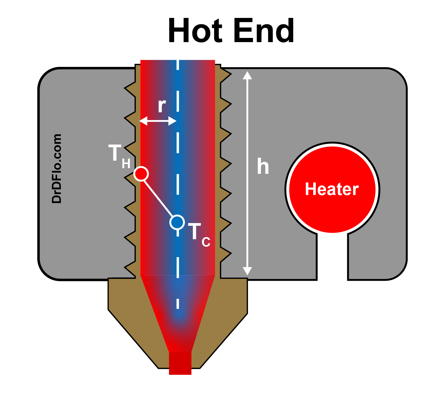
The energy required to heat the plastic is provided by the hot end. Heat conducts from hot to cold objects (e.g., heat leaving your hand when you touch an ice cube). But important questions for a high flow rate extruder are how long does it take for the heat to conduct from the hot end throughout the filament? And how can we speed this heat transfer up? Fourier’s Law helps explain heat transfer through conduction in a hot end (Figure 15). Fourier’s Law states that the amount of heat flow (Q) is proportional to the area (A) in the normal direction of the heat flow, the temperature difference between the hot end wall and the coldest part of the filament, the core (TH - TC), and inversely proportional to ½ the thickness of the filament (r). The constant k is the thermal conductivity of the plastic.
Q = k (A/r) (TH - TC)
This equation reveals the two practical ways to increase the amount of heat flow, which will result in more melted plastic:
- Increase the temperature of the hot end.
- Increase the surface area between the hot end and the plastic.
Turning up the temperature of the hot end for increased melting is one of the reasons why PLA is printed anywhere from 190 to 220C even though it melts at 150C. However, there is a limit on the temperature of the hot end before the polymer next to the hot end wall degrades (i.e., burns). So, it is not possible to double the temperature of the hot end to get twice the flow rate.
Please note: When shopping for a high flow extruder, any flow rate reported by the manufacturer needs to be accompanied by the plastic type and extrusion temperature used or else this information is not meaningful. Most companies are extruding PLA at temperatures between 210 C and 220 C, which makes it possible to compare between models.
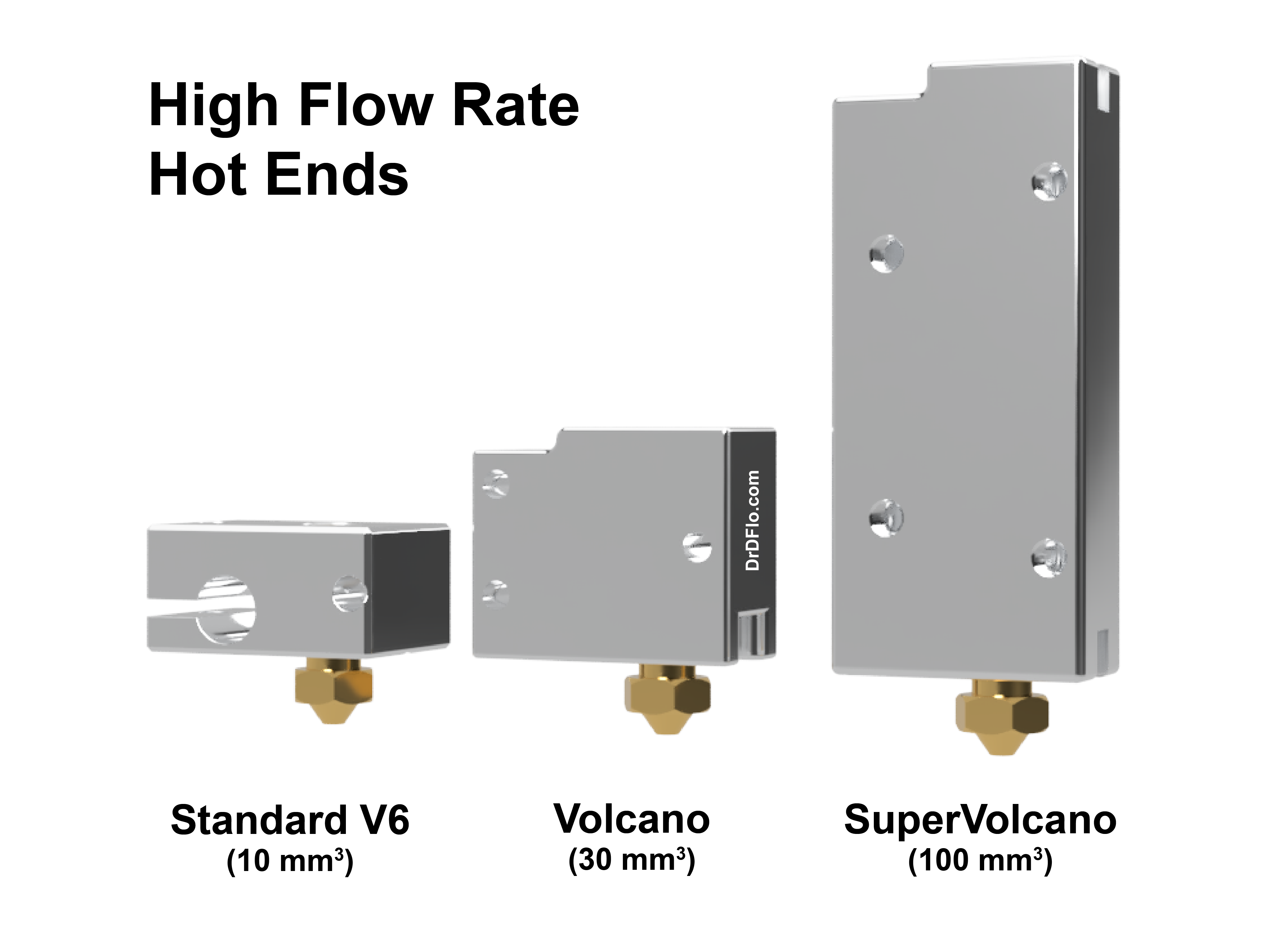
Increasing the surface area between the hot end and the filament is the best approach to increase flow rate without having deleterious effects on the properties of the filament. The path that the filament takes through the hot end is cylindrical shaped. On a V6 hot end that melt path is approximately 1 mm in diameter and 12 mm in length. The surface area in contact with the filament would be: 2πrh = 2π(1 mm)(12 mm)= 75.4 mm2. The surface area can be increased by in turn increasing the radius of the melt path or its length. Increasing the radius is not ideal for several reasons, including a larger volume of polymer melt held up in the hot end and a longer distance for the heat to travel to melt the filament entirely. The path length can be increased with only a modest increase in the melt volume and does not change B from Fourier’s Law. For these reasons, nearly all high flow rate extruders have a hot end that is stretched along the length of the filament path (Figure 16).
Sizing a Heater for High Flow Rate Extrusion
To heat more filament in a larger hot end, a more powerful ceramic heater cartridge is needed. Let’s perform a quick back-of-the-envelope calculation to get a ballpark for how much energy is required to melt an ABS filament that is being printed in a high flow rate extruder at 30 mm3. Heat capacity or specific heat is the amount of energy required to raise the temperature of a material by one degree. The specific heat of ABS is approximately 2.0 Joules per gram (J/g) per ℃. ABS technically does not have a defined melting point because it is amorphous, but let’s assume that the temperature of the filament needs to be raised 200 ℃ for it to have the right flowability (i.e., low enough viscosity) to be printed. With a density of 1.0 g/cm3 and a flow rate of 30 mm3, 0.03 g of ABS needs to be melted and extruder every second. To raise 0.03 g of ABS to printing temperature, then 0.03 g * 200 ℃ * 2.0 J/(g * ℃) = 12 J are required. Because the printing process is continuous, 12 J are needed every second. Watts, which is the power rating for heating elements are equal to J/s So, a 12 W ceramic heater cartridge is needed. Generally, a 40W heater is recommended for a high flow rate extruder, so what is the discrepancy between the calculated value and the recommended value?
Well, the first calculation assumed that all heat produced by the ceramic heater would be used for melting the filament. In reality, there is a significant loss of heat to the surrounding air through convection and radiation. It is difficult to calculate the exact heat loss due to variable forced air cooling from the print head moving and the cold end fan, but the Engineering ToolBox provides an online calculator for getting a close estimate. Convective heat transfer increases with surface area, and as was discussed previously, high flow rate extruders have larger hot ends. I have estimated that a Volcano hot end will lose 10 W of heating to the surrounding air during a print. Consequently, this extruder would need at least 22 J. The downside of using an underpowered heater is incomplete melting and jamming. Using a heater cartridge that is too powerful really has no downsides when wired and controlled properly.
Extruder Purchasing Guide
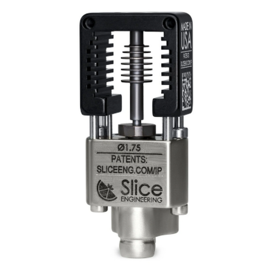
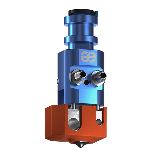
Slice Engineering Mosquito Magnum+ Hotend
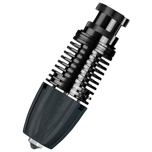
TriangleLab/Phaetus Rapido
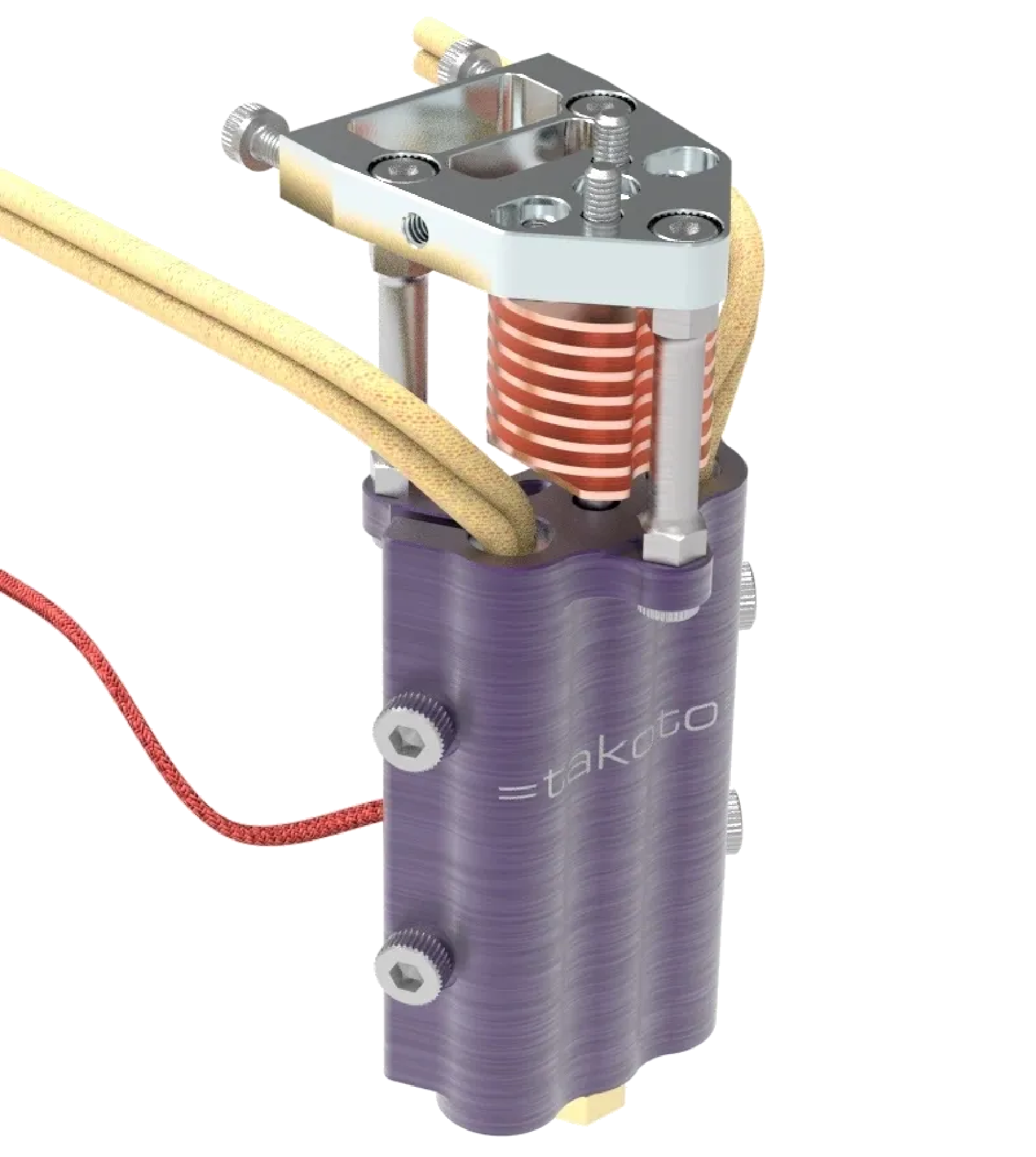
Takoto HE20/HE50
| Model | Manufacturer | Max Flow Rate (mm3/sec)* | Max Printing Temperature (℃) | Filament Diameter | Height (mm) |
|---|---|---|---|---|---|
| Volcano | E3D | 30 | 500 | 1.75 | 70 |
| Mosquito Magnum | Slice Engineering | 30 | 500 | 1.75 | 41 |
| HE20 | Takoto | 30 | > 320 | 1.75 | 47 |
| Dragon HF | TriangleLab/Phaetus | 31.5 | 500 | 1.75 | 62 |
| Dragon UHF | TriangleLab/Phaetus | 42 | 500 | 1.75 | 80 |
| Rapido | TriangleLab/Phaetus | 45 | 500 | 1.75 | 80 |
| HE50 | Takoto | 55 | > 320 | 1.75 | ? |
| Mosquito Magnum + | Slice Engineering | 88 | 500 | 1.75 | 60 |
| SuperVolcano | E3D | 100 | 500 | 1.75 | 100 |
| Typhoon | Dyze | 200 | 500 | 2.85 | 224 |
High Temperature Extruders
FFF 3D printing has largely been focused on printing commodity plastics (PLA, ABS, PETG), which are easy to print due to their low melting and crystallization temperatures, but their poor mechanical properties limit their use. For this reason, 3D printing enthusiasts have their eyes set on engineering (PC, Nylon) and high-performance plastics (PEEK, Ultem). These plastics have improved mechanical, chemical, and thermal properties compared to commodity plastics. However, they have higher melting points and are more likely to warp. Consequently, a high temperature extruder and often chamber heating are required to melt these polymers and prevent temperature gradients that would otherwise result in warping.
Hot ends that are capable of melting performance plastics at temperatures > 300 ℃ are readily available and will be covered in this section. However, the second requirement of actively heating the printing enclosure to temperatures > 100 ℃, which is necessary for high-performance plastics, poses quite a few challenges, as most motors permanently demagnetize above 80 ℃, preventing the use of a normal cold end fan or extrusion drive motor inside of the enclosure. Water cooling the cold end is a must for when printing these specialized plastics. In the future, a dedicated article on all the requirements and considerations for high temperature printing will be published, but for now we will focus on the extruder. Further, printing engineering plastics (PC, Nylon) are possible on enclosed hobbyist machines equipped with high temperature extruders but without dedicated chamber heaters. These engineered plastics are also the target of this section.
PTFE Lined Extruder (Low Temperature)
Perhaps, the most important differentiating factor between a high-temperature and low-temperature extruder is how far the PTFE (AKA Teflon or Bowden) tube extends into the extruder. It is important to restrict the path of the filament between the extrusion drive and the hot end to convert all the motor’s torque into pushing molten plastic out of the nozzle. Nearly all extruders use a PTFE tube with an inside diameter that matches the filament’s to prevent the plastic from wandering off its path. Older extruder design’s such as the E3D Lite6 or MakerGear’s V4 have the PTFE tube extend all the way into the hot end, which is known as a PTFE lined extruder. Recently, a strong negative perception of this design has developed, but there are several significant benefits:
- Improved retraction. The slick surface of PTFE prevents the plastic from sticking to the wall of the hot end during retraction.
- Less stringing and clogging. PTFE is an insulator, which prevents premature melting of the filament (i.e., heat creep) before reaching the nozzle.
- Flexible filament optimized. A confined PTFE tube path is especially important for flexible TPUs that are difficult to push on.
The 3D printer community has taken issue with the PTFE lined extruder because PTFE has a maximum operating temperature ranging from 240 to 260 ℃, depending on the quality/manufacturer. This limits this type of extruder to lower temperature melting plastics (PLA, TPU, and some ABS variants). Further, even within this temperature window, the PTFE liner will have to be replaced eventually. However, if you plan to print almost exclusively with PLA and TPUs, then the improved print quality, hassle free prints, and low cost make these extruders an excellent choice. I always recommend the E3D Lite6 to schools and makerspaces focused on PLA printing.
All-Metal Extruder (High Temperature)
An “all-metal” extruder does not have a PTFE liner that extends into the hot end and thus, are not restricted by the degradation temperature of PTFE. However, most all-metal extruders still use a PTFE tube to connect the extrusion drive and cold end, so the presence of a PTFE tube does not differentiate an all-metal extruder from a PTFE-lined one. Most new extruders are all-metal, which is evident from their marketing terms (e.g., “all-metal,” “high temperature,” etc.) or stating a maximum extrusion temperature higher than 250 ℃. I have yet to come across an all-metal extruder that is not capable of extruding at least PC at 300 C. However, for extreme temperatures >> 300 ℃, there are 3 other requirements:
- A copper or steel hot end block. 6061 aluminum, a common material for hot end blocks, rapidly loses its strength when heated above 300 ℃ for extended durations. Therefore, alloys that possess higher thermal stability for larger temperature windows are required. Nickel plated copper blocks are the most popular.
- High wattage ceramic heater cartride. 40 W is sufficient for 300 ℃, but a 60 or 70 W should be used for even higher temperatures. Currently, PTC heaters found on E3D’s Revo extruders cannot reach temperatures > 300 ℃
- Appropriate temperature probe. As discussed in the Temperature Sensor section, thermistors have a narrow but accurate temperature range, so the standard 100k thermistor will not accurately measure temperatures > 300 ℃. Therefore, a 450 ℃ thermistor or the less accurate (but larger temperature range) PT1000 RTD should be used.
Printing high temperature plastics can also benefit from a longer/larger hot end. A longer heated path provides more time for heat energy to conduct from the hot end to the filament. By definition, high temperature plastics require a significant amount of energy to melt and failure to melt the filament completely will cause the extruder to clog and jam. Extruders with this extra melt zone length are typically denoted as high flow rate (HF) as this feature is also useful when printing at high volumetric flow rates (i.e., melting a lot of plastic quickly). The drawback of this extended hot end is that the larger melt region is more likely to ooze especially when printing commodity plastics. Below are three extruders recommended for high temperature printing. Please note: All the standard extruders mentioned previously are all-metal and capable of extruding PC. The list below is focused on true high-temperature extrusion >> 300 ℃.
Slice Engineering Mosquito Magnum+ Hotend
Phaetus Dragon Hotend WHF
Dyze Pro
Trianglelab TD6S
External Resources
There are a lot of different ways to successfully build a 3D printer, many of which are not covered on this website. If you want to learn more about FFF extruders, then click through some of the links below to external websites and forums.